


ROYAL ENFIELD WORKSHOP MANUAL
Section C14 Page 7
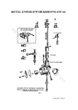
Check the pump disc springs for fatigue by
assembling in the timing cover and placing the
pump covers in position. The latter should be held
1/8 in. off the timing cover if the springs are
correct.
In the case of the 500 c.c. engine see that the
steel end pads are in position on the outer ends of
the springs.
The pump spindle should be renewed if
excessive wear has taken place on the teeth.
Reassemble the oil pumps, replacing the paper
cover gaskets if necessary. Before fitting each
cover fill the pump chamber with clean oil.
Having assembled the pumps, lay the timing
cover flat and fill the oil ports by means of an oil
can. Turn the pump spindle with a screwdriver in
a clockwise direction looking on the front and it
can then be seen whether the pumps are operating
correctly.
Before replacing the timing cover on the
engine, fill the filter chamber with clean oil.
The oil feed to the big end can be checked by
partially unscrewing the feed plug in the timing
cover between the oil pumps while the engine is
running and the oil return to the tank can be
checked by removing the oil filler cap.
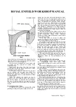
17. Removal of Pump Worm and Timing
Pinion
Remove the timing cover as described in
Subsection 1.
Unscrew the worm shaft by a hexagon head
behind the worm, using Special Tool No. E.5451.
This is a left-hand thread.
Withdraw the timing pinion by means of a flat
chisel placed behind the pinion and tapped gently.
When refitting the timing cover see that the
cork or rubber plug is in position in the hole in
the pump worm and is undamaged.
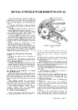
18. Removal of the Magneto or Contact
Breaker Pinion Unit
After first removing the timing cover of an
engine having magneto ignition, the pinion of the
type which incorporates an auto-advance unit is
removed by unscrewing the centre nut. This will
draw the pinion and auto-advance unit of the
shaft.
Coil ignition models: The auto-advance
mechanism in this case is in the contact breaker
unit, and the pinion is drawn off by removing the
securing nut and operating the extractor tool.
The "Works Replica," which employs
magneto ignition, but no auto-advance
mechanism, also follows this procedure.
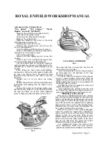
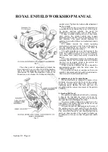
19. Primary Chain Adjustment
Access to the primary chain adjuster is gained
by removing the primary chain cover, which is
To take up slack in the primary chain, unscrew the
locknut and turn the adjuster beneath the curved slipper
until correct chain tension is obtained; retighten the
locknut.
held in position by a single nut. Before removing the
nut, place a tray under the engine to catch the oil
from the chaincase.
Beneath the bottom run of the chain is a curved
slipper on which the chain rests and which may be
raised or lowered by turning the adjusting screw after
having first slackened the locknut.
The chain should be adjusted so that there: is ¼ in.
up and down movement at the centre of the top run
of the chain.
After replacing the chain cover remember to
replenish the chaincase with oil.
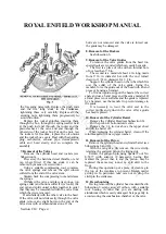
20. Removal of the Engine and Clutch Sprockets
The primary chain is endless so that it is
necessary to remove both the engine and clutch
sprockets simultaneously.
Remove the alternator stator by undoing three
fixing screws.
Remove the central hexagon nut securing the
alternator rotor, which can then be drawn off, taking
care not to lose the key.
Unscrew the engine sprocket nut using Special
fool No. E.4877. The engine sprocket is mounted on
splines and can then be removed with the clutch
sprocket.
To remove the clutch sprocket unscrew tile
clutch spring pins then lift away the spring cap,
springs and distance pieces, clutch front plate, centre
www.hitchcocksmotorcycles.com
Содержание 350 BULLET 1956
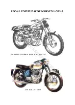
Страница 3: ...ROYAL ENFIELD WORKSHOP MANUAL 350 BULLET 1961 w w w h i t c h c o c k s m o t o r c y c l e s c o m ...
Страница 5: ...ROYAL ENFIELD WORKSHOP MANUAL 500 BULLET 1956 w w w h i t c h c o c k s m o t o r c y c l e s c o m ...
Страница 7: ...ROYAL ENFIELD WORKSHOP MANUAL w w w h i t c h c o c k s m o t o r c y c l e s c o m ...
Страница 21: ...ROYAL ENFIELD WORKSHOP MANUAL 350 CLIPPER 1958 w w w h i t c h c o c k s m o t o r c y c l e s c o m ...
Страница 23: ...ROYAL ENFIELD WORKSHOP MANUAL Section E1 Page 2 w w w h i t c h c o c k s m o t o r c y c l e s c o m ...
Страница 28: ...ROYAL ENFIELD WORKSHOP MANUAL Section F4 Page 3 w w w h i t c h c o c k s m o t o r c y c l e s c o m ...
Страница 30: ...ROYAL ENFIELD WORKSHOP MANUAL Section F4 Page 5 w w w h i t c h c o c k s m o t o r c y c l e s c o m ...
Страница 42: ...ROYAL ENFIELD WORKSHOP MANUAL Section H5 Page 1 w w w h i t c h c o c k s m o t o r c y c l e s c o m ...
Страница 57: ...ROYAL ENFIELD WORKSHOP MANUAL w w w h i t c h c o c k s m o t o r c y c l e s c o m ...
Страница 69: ...ROYAL ENFIELD WORKSHOP MANUAL w w w h i t c h c o c k s m o t o r c y c l e s c o m ...
Страница 71: ...ROYAL ENFIELD WORKSHOP MANUAL Section M2 Page 2 w w w h i t c h c o c k s m o t o r c y c l e s c o m ...
Страница 72: ...ROYAL ENFIELD WORKSHOP MANUAL Section M2 Page 3 w w w h i t c h c o c k s m o t o r c y c l e s c o m ...
Страница 73: ...ROYAL ENFIELD WORKSHOP MANUAL Section M2 Page 4 w w w h i t c h c o c k s m o t o r c y c l e s c o m ...
Страница 74: ...ROYAL ENFIELD WORKSHOP MANUAL Section M2 Page 5 w w w h i t c h c o c k s m o t o r c y c l e s c o m ...
Страница 75: ...ROYAL ENFIELD WORKSHOP MANUAL Section M2 Page 6 w w w h i t c h c o c k s m o t o r c y c l e s c o m ...
Страница 76: ...ROYAL ENFIELD WORKSHOP MANUAL Section M4 Page 1 w w w h i t c h c o c k s m o t o r c y c l e s c o m ...
Страница 77: ...ROYAL ENFIELD WORKSHOP MANUAL w w w h i t c h c o c k s m o t o r c y c l e s c o m ...
Страница 79: ...ROYAL ENFIELD WORKSHOP MANUAL Section P1 Page 2 w w w h i t c h c o c k s m o t o r c y c l e s c o m ...
Страница 80: ...ROYAL ENFIELD WORKSHOP MANUAL Section P1 Page 3 w w w h i t c h c o c k s m o t o r c y c l e s c o m ...


