www.rotortool.com
Luftzufuhr-Rohre /
Air feed tubes
9
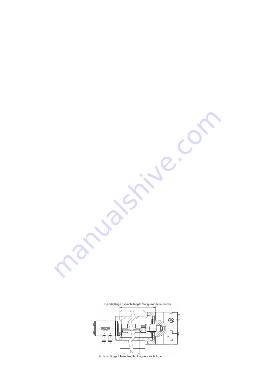
4. Den Flexschlauch in die Spindeldurchfüh-
rung einführen und das Futter an der Spin-
delnase festschrauben. Die Montage des
Futters ist gemäss der entsprechenden
Betriebsanleitung vorzunehmen.
ROTOR Betriebsanleitungen siehe auch unter
www.rotortool.com
5. Den Flexschlauch evtl. ablängen und wie
folgt an die Drehdurchführung anschliessen:
schwarz an A = öffnen; blau an B = schlies-
sen, grau an C/E = zentrale Zufuhr (z. B. Kühl-
mittel/Luft)
6. Drehdurchführung auf die max. zulässige
Rundlaufabweichung von 0.02 mm ausrich-
ten, Schrauben festziehen.
7. Zuleitungsschläuche am Drehverteiler
anschliessen. Vor der Zuleitung der Luft in
das Luftzufuhr-Rohr muss eine Luftwar-
tungseinheit bestehend aus Manometer,
Wasserabscheider, Feinfilter und Oeler einge-
baut werden.
WICHTIG!
der Spannvorgang muss mittels
einem Druckwächter überwacht werden
(siehe Pneumatik-Schema auf Seite 10).
8. Haltegabel (ist vom Kunden zu fertigen)
montieren. Die Haltegabel ist so anzubrin-
gen, dass sie an den Luftverschraubungen
angreifen kann. Möglichst leichte Schläuche
verwenden. Es dürfen keine zusätzlichen
Radial- oder Axial-Kräfte durch die Rückhalte-
rung oder Schläuche auf den Stator
einwirken.
9.
WICHTIG!
Bevor auf C, die zentrale Zufuhr,
Kühlmittel usw. eingeleitet wird muss
geprüft werden, ob das Futter korrekt öff-
net / schliesst., d. h. korrekt angeschlossen ist.
Gelangt über die Anschlüsse A oder B Kühl-
mittel in die Pneumatik des Präzisions-
Spannfutters muss Dieses zur Reinigung
möglichst umgehend ROTOR zugestellt wer-
den. Wird das Futter nicht umgehend korrekt
demontiert / montiert kann im Pneumatik-
Zylinder Rost ansetzen. Wird das Futter nicht
korrekt demontiert / montiert ist die Rund-
laufgenauigkeit nicht mehr gewährleistet
4. Insert the flexible hose into the spindle and
screw the chuck to the spindle nose. The
assembly of the chuck must be carried out
according to the corresponding operating
instructions. For ROTOR manuals, also see
www.rotortool.com
5. If required, cut the flexible hose to length and
connect to the rotary union as follows:
black to A = open; blue to B = close, grey to
C/E = central supply (e. g., coolant/air)
6. Align the rotary union to the max. permissible
concentricity deviation of 0.02 mm, tighten
screws.
7. Connect the supply hoses to the rotary union.
Before feeding the air into the air feed tube,
an air conditioning unit consisting of a
manometer, water separator, fine filter and
oiler must be installed.
IMPORTANT!
the clamping process must be
monitored by means of a pressure monitor
(see Pneumatic diagram on page 10).
8. Mount the holding bracket (to be manufac-
tured by the customer). The holding bracket
is to be attached so that it can engage the air
connectors. Use the lightest hoses possible.
The stator must not be subject to any addi-
tional radial or axial forces acting through the
holder or the hoses.
9.
IMPORTANT!
Before initiating on C, the cen-
tral supply, coolant, etc., it must be checked if
the chuck opens / closes correctly, i. e. is con-
nected correctly. If coolant enters the pneu-
matics of the precision chuck via connections
A or B, it must be delivered to ROTOR as soon
as possible for cleaning. If the chuck is not cor-
rectly disassembled / assembled immediately,
rust can start to develop in the pneumatic cyl-
inder. If the chuck is not disassembled / assem-
bled correctly, concentricity is no longer
guaranteed.
Type BF / BFA / BFC / BFCA / CF / CFA / CFC
Содержание LZR-B
Страница 1: ...Betriebsanleitung Luftzufuhr Rohre Operating manual Air feed tubes www rotortool com...
Страница 2: ......


