www.rotortool.com
Luftzufuhr-Rohre /
Air feed tubes
7
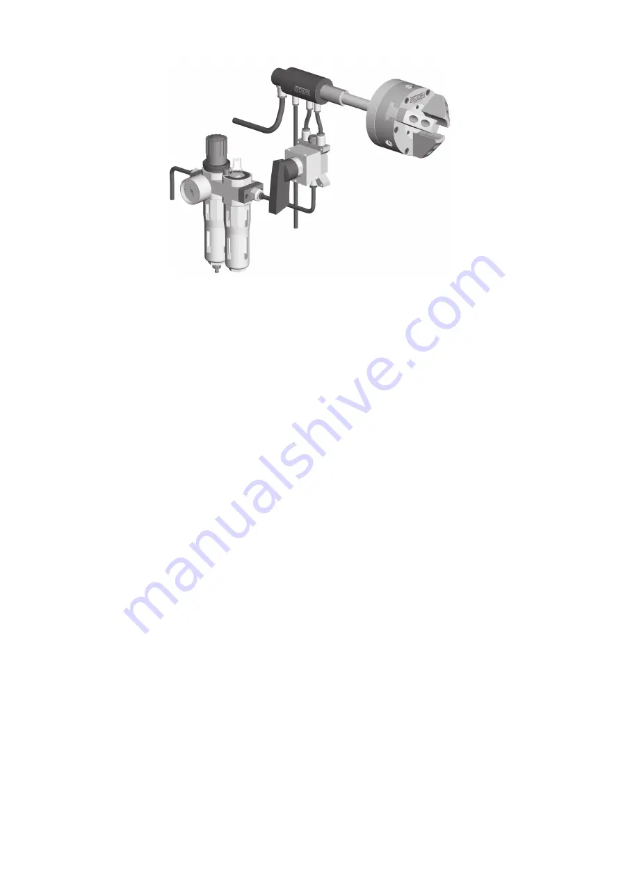
2.2 Systemaufbau
2.2 System design
2.3 Montage der Luftzufuhr-Rohre
Luftzufuhr-Rohre bestehend aus festen Rohren
1. Rohr-Führungsflansch in das Maschinen-
Spindelende einpassen, im
∅
ca. 0.2 mm
kleiner als die Bohrung, sodass das Luftzu-
fuhr-Rohr auf die max. zulässige Rundlauf-
abweichung justiert werden kann.
Führungsflansche zum klemmen, Typ B-FF
und F-FF, einpassen im
∅
0.03 mm kleiner als
die Bohrung, sodass in geklemmtem Zustand
das Luftzufuhr-Rohr sich axial frei bewegen
kann.
2. Bei Rohrlänge > 600 mm und Drehzahlen
über 1’000 min
–1
das Rohr in der Spindelmit-
te zusätzlich mit einem Stützring abstützen.
Stützring im A-
∅
ca. 0.03 mm kleiner als die
Spindel-Bohrung. Dabei ist darauf zu achten,
dass das Rohr sich axial frei bewegen lässt.
3. Das Gewinde reinigen und das Rohr von
Hand mittels dem Rändelring resp. Füh-
rungsflansch in das bereits montierte Futter
einschrauben und festziehen.
Bitte keine Zange verwenden um Deformati-
on des Gewindes und Bruch der Klebestellen
zu vermeiden.
4. Führungsflansch an Maschinenspindel fest-
schrauben, die mitgelieferten Sechskant-
schrauben am Zwischenflansch festziehen.
5. Schrauben am Führungsflansch nochmals
leicht lösen und das Luftzufuhr-Rohr auf die
max. zulässige Rundlaufabweichung von
0.02 mm ausrichten, Schrauben festziehen.
6. Flexible Schläuche anschliessen.
A/B = öffnen / schliessen
C = Kühlmittel / Fett
E = nur Luft!! (keine Flüssigkeiten)
D = Entlastungs- / Leckageanschluss
2.3 Mounting the air feed tubes
Air feed tubes consisting of fixed pipes
1. Fit the pipe guide flange into the machine
spindle end approx. 0.2 mm smaller than the
bore in the
∅
so that the air feed tube can be
adjusted to reach the max. permissible con-
centricity deviation.
Fit clamping guide flanges type B-FF and F-FF
smaller than the bore in
∅
0.03 mm so that
the air feed tube is free to move axially when
clamped.
2. For tube lengths > 600 mm and speeds over
1,000 rpm, the tube must be given additional
support at the middle of the spindle by a sup-
port ring. Support ring in A-
∅
approx. 0.03
mm smaller than the spindle bore.
Please ensure that the tube can move freely in
the axial direction.
3. Clean the thread and then screw the tube into
the chuck and tighten it by hand using the
knurled ring or guide flange.
Please do not use pliers as these might deform
the thread or break the splices.
4. Tighten the guide flange to the machine spin-
dle and tighten the hexagon bolts provided on
the intermediate flange.
5. Slightly loosen the screws on the guide flange
again and align the air feed tube to the maxi-
mum permitted runout of 0.02 mm, tighten
the screws.
6. Connect up the flexible hoses.
A/B = open / close
C = coolant / grease
E = only air!! (no liquids)
D = discharge / leakage connection
Содержание LZR-B
Страница 1: ...Betriebsanleitung Luftzufuhr Rohre Operating manual Air feed tubes www rotortool com...
Страница 2: ......


