Rose Point Radar Installation Guide
2
Power Supply
For the radar sensor to be operated normally, the power supply (battery) detailed in “Power Supply
Requirements” is required. Note also that if the battery is discharged, its voltage may fluctuate greatly,
causing the radar to malfunction. When starting up the radar system or beginning transmission, an
additional rush current is required on the power line. Carefully check the power supply system including
wiring by using a circuit tester.
Power Supply Requirements
The radar sensor power supply may provide anywhere from 10.2 to 41.6 VDC. The following table
describes the current requirements at 12 and 24 VDC.
12 VDC
24 VDC
MDS-51
5A
2.5A
MDS-52
6A
3A
MDS-61
7A
3.5A
MDS-62
8A
4A
Fuse Requirements
For the radar sensor to be operated safely, fuses with the proper rating must be used.
Supply Voltage to Fuse Table for MDS-51
Supply Voltage to Fuse Table for MDS-52
Supply Voltage to Fuse Table for MDS-61
Supply Voltage to Fuse Table for MDS-62
Note: Fuses marked* are included with your radar
Содержание MDS-51
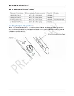
Страница 13: ...Rose Point Radar Installation Guide 10 Attaching the Cover Radome scanner ...
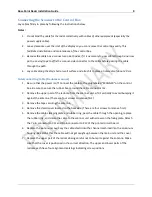
Страница 14: ...Rose Point Radar Installation Guide 11 Attaching the interconnecting cable Radome Scanner ...
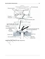
Страница 16: ...Rose Point Radar Installation Guide 13 Attaching the interconnecting cable Open Array Scanner ...
Страница 26: ...Rose Point Radar Installation Guide 23 Specifications Radar Sensor Unit Power Interface ...
Страница 27: ...Rose Point Radar Installation Guide 24 Drawings Interconnection Diagram ...
Страница 28: ...Rose Point Radar Installation Guide 25 RB715A Scanner Unit ...
Страница 29: ...Rose Point Radar Installation Guide 26 RB716A Scanner Unit ...
Страница 30: ...Rose Point Radar Installation Guide 27 RB717A 718A Scanner Unit ...
Страница 31: ...Rose Point Radar Installation Guide 28 MDS 5 MDS 6 Control Box ...


