


Rose Point Radar Installation Guide
4
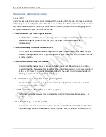
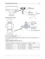
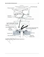
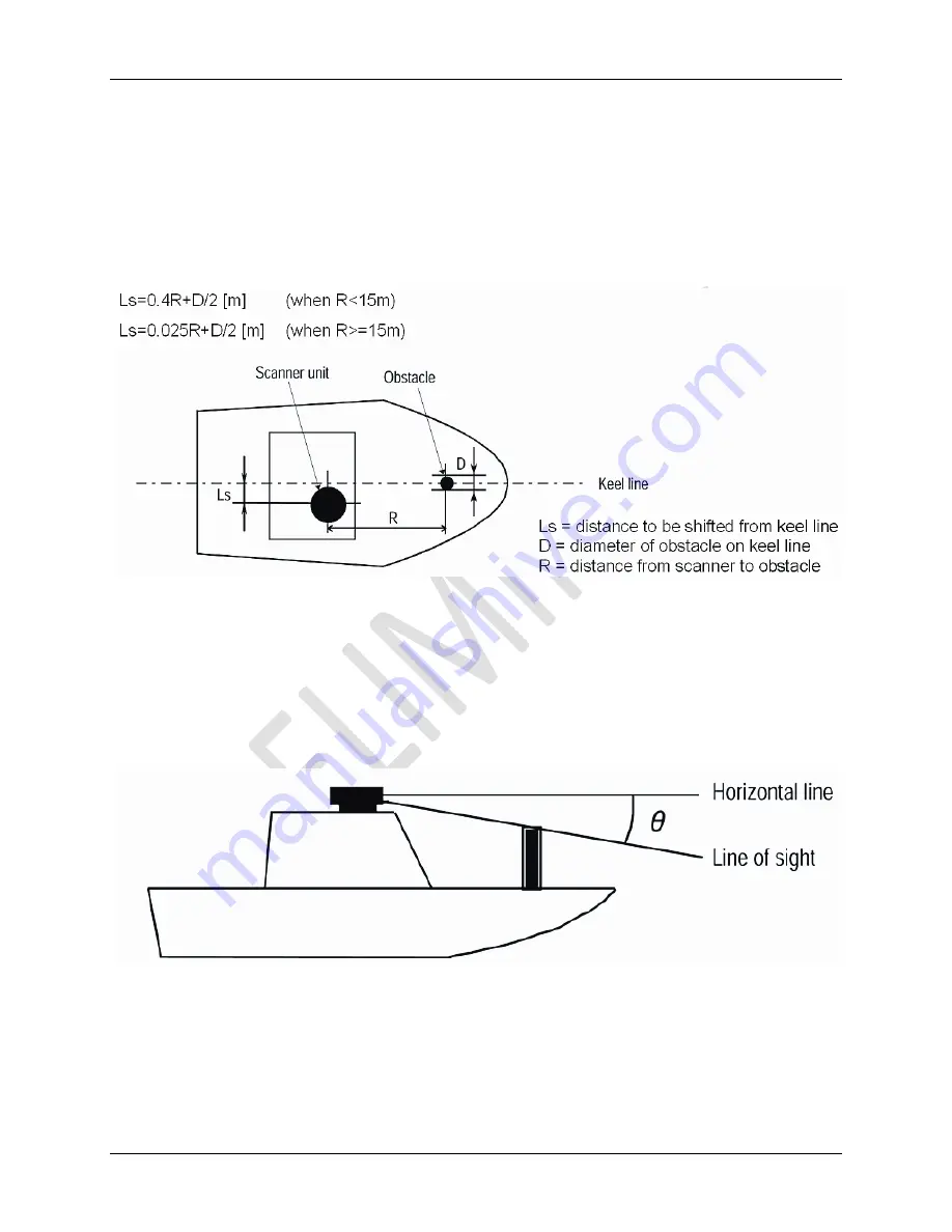
Shifting Away from Obstacles
Shifting from keel line
By shifting the scanner position from the keel line to one side of the ship, it is possible to move shadow
zones to the other side which makes it possible to keep clear vision in the bow direction. The distance to
be shifted can be obtained
by calculation depending on the distance from the scanner to obstacles using the
following equation:
Shifting from keel line
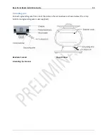
Obtaining sufficient dip angle
Raise the scanner position so that there is a sufficient dip angle (available between the line of sight from
the scanner to the obstacle and the horizontal line.) By raising the dip angle above 5 degrees, it is
possible to prevent mid- and long-distance shadow zones. The radar cannot detect objects below the
line of sight.
Obtaining sufficient dip angle
Содержание MDS-51
Страница 13: ...Rose Point Radar Installation Guide 10 Attaching the Cover Radome scanner ...
Страница 14: ...Rose Point Radar Installation Guide 11 Attaching the interconnecting cable Radome Scanner ...
Страница 16: ...Rose Point Radar Installation Guide 13 Attaching the interconnecting cable Open Array Scanner ...
Страница 26: ...Rose Point Radar Installation Guide 23 Specifications Radar Sensor Unit Power Interface ...
Страница 27: ...Rose Point Radar Installation Guide 24 Drawings Interconnection Diagram ...
Страница 28: ...Rose Point Radar Installation Guide 25 RB715A Scanner Unit ...
Страница 29: ...Rose Point Radar Installation Guide 26 RB716A Scanner Unit ...
Страница 30: ...Rose Point Radar Installation Guide 27 RB717A 718A Scanner Unit ...
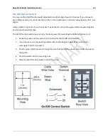
Страница 31: ...Rose Point Radar Installation Guide 28 MDS 5 MDS 6 Control Box ...