


Rose Point Radar Installation Guide
16
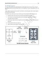
On/Off Control Switch
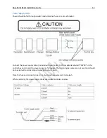
You may use the On/Off control switch provided or another style of switch if desired. If you choose to
use a different style, it must be rated for 30 VDC or more and have a current carrying capacity of 0.1 A or
higher.
Using a switch is optional. If you choose not to use a switch, connect the green and blue wires together
and cover with electrical tape.
The On/Off control switch does not carry the main power for operating the RADARpc scanner unit.
1.
Route the green and blue wires to the location for the On/Off control switch.
2.
If you choose to use the switch provided, refer to the diagram below to layout and cut a
rectangular hole for the switch.
3.
Pass the green and blue wires through the hole from behind the panel and connect the wires to
the switch.
4.
Press the switch into the mounting hole.
5.
Place the On/Off control switch in the Off position.
Содержание MDS-51
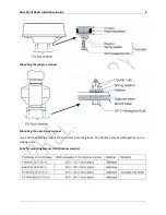
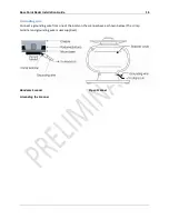
Страница 13: ...Rose Point Radar Installation Guide 10 Attaching the Cover Radome scanner ...
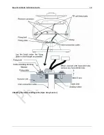
Страница 14: ...Rose Point Radar Installation Guide 11 Attaching the interconnecting cable Radome Scanner ...
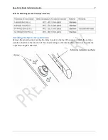
Страница 16: ...Rose Point Radar Installation Guide 13 Attaching the interconnecting cable Open Array Scanner ...
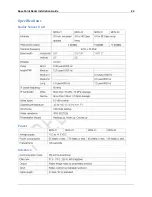
Страница 26: ...Rose Point Radar Installation Guide 23 Specifications Radar Sensor Unit Power Interface ...
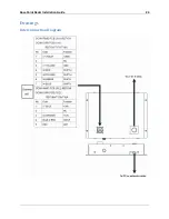
Страница 27: ...Rose Point Radar Installation Guide 24 Drawings Interconnection Diagram ...
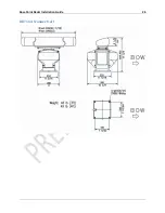
Страница 28: ...Rose Point Radar Installation Guide 25 RB715A Scanner Unit ...
Страница 29: ...Rose Point Radar Installation Guide 26 RB716A Scanner Unit ...
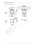
Страница 30: ...Rose Point Radar Installation Guide 27 RB717A 718A Scanner Unit ...
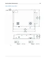
Страница 31: ...Rose Point Radar Installation Guide 28 MDS 5 MDS 6 Control Box ...