4-44
4
[ ]
CUTTING MENU
PRINT-CUT ADJ.
PRINT-CUT ADJ.
SETTING
F:+0.30 +0.30mm
S:-0.40 -0.40mm
[ ]
[ ]
[ ]
6
[ ]
CUTTING MENU
PRINT-CUT ADJ.
PRINT-CUT ADJ.
TEST PRINT
[ ]
7
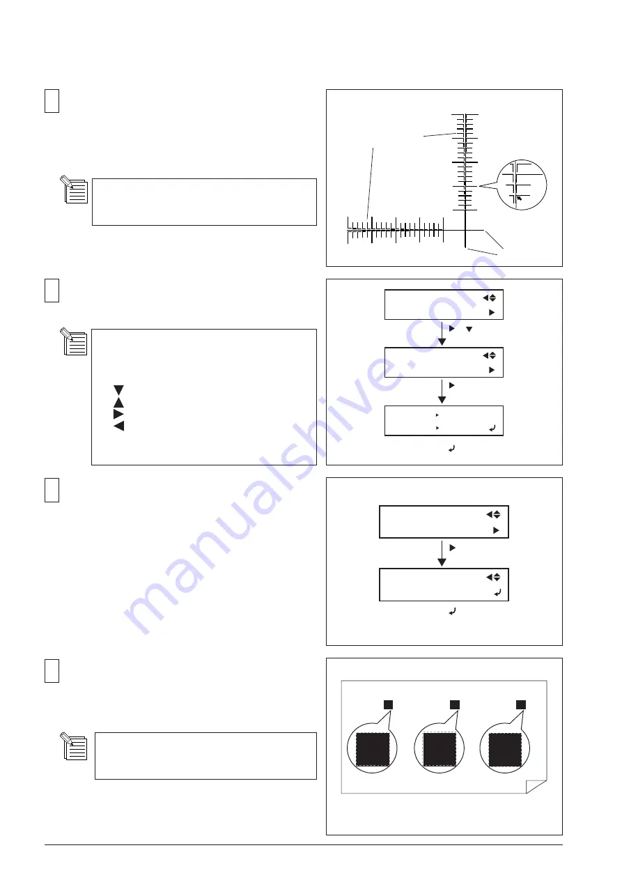
From the test pattern, find the value where the print line
matches the cut line.
In this case, the correction value for the scan direction is
"-0.3".
If it is difficult to see the cut line visually, use
a magnifier.
+2.0
-2.0
+1.0
-1.0
+0.5
-0.5
+0.0
-0.0
+1.5
-1.5
Scan
+2.0
-2.0
+1.0
-1.0
+0.5
-0.5
+0.0
-0.0
+1.5
-1.5
Feed
-0.5
<TEST PATTERN>
Correction-value scale
Cut line
F: Feed direction S: Scan direction
Left: Current value Right: New value
(Setting range: +/-5.00mm In 0.01mm unit)
key : Value of F, t
key : Value of F, towards -
key : Value of S, t
key : Value of S, towards -
ENTER key : Saves new setting
MENU key : Moves out SETTING menu
5
Select [CUTTING MENU]> [PRINT-CUT ADJ.]>
[SETTING], and enter the correction-values found in the
test pattern for both Feed and Scan.
Select [PRINT-CUT ADJ.]> [TEST PRINT], and press
[ENTER] key.
The test print and cut will be performed.
3 marks are printed at the left-end, right-end and the
center of the media, and each mark is cut. Confirm the
cut line positions on the marks visually.
If it is difficult to see the cut line visually, use
a magnifier.
Broken line is indicating the cut line
Содержание VersaCamm VP-300
Страница 39: ...2 4 2 MAIN BOARD_Arrangement Diagram Soldering Side ...
Страница 50: ...2 15 2 SERVO BOARD_Arrangement Diagram Soldering Side ...
Страница 58: ...2 23 2 2 5 SUB BOARD It indicates the version of the Board SUB BOARD_Arrangement Diagram Component Side ...
Страница 102: ...3 39 Move the Head Carriage by hand to the lock position HEADCARRIAGE Fix the I S Cover SCREW I SCOVER HOOK 20 21 ...
Страница 222: ...7 2 7 Unpacking Manual etc CD ROM etc ...


