9
Panel Descriptions
Multi-View Display
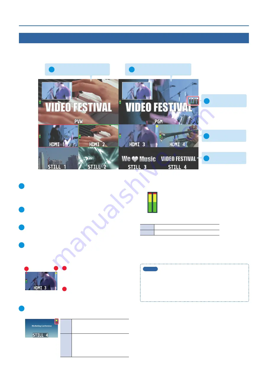
This unit supports multi-view output. This feature lets you split up the screen into sections and display the final output video, preview video, input
video and so on with an external monitor.
The multi-view is output from the OUTPUT 2 connector by factory default.
1
PVW (preview) section
2
PGM (program) section
1
PVW (preview) section
Displays the preview output video (the video to be output next).
* The fade-in/out effect (p. 23) is not reflected here.
2
PGM (program) section
Displays the final output video.
3
Audio level meter
Displays the level meter for audio input from the audio jacks.
4
Input videos section
Displays video input via INPUT 1–4 connectors.
The final video output and preview output video (the video to be
output next) are displayed with tally frames.
1
2
1
REC indicator
If a camera that supports the REC status
function is connected, this is shown
when the camera’s REC button is pressed.
2
PinP indicator
Shows that this has been selected as a
video source for PinP compositing.
5
Still images section
Shows the loaded still images (p. 20, 21).
Yellow
PinP indicator
Shows that this has been selected as
a video source for PinP compositing.
Red
STILL indicator
Shows that a still image is being output.
* Only when pressing the [1/5]–[4/8]
buttons and outputting a still image
(p. 22).
Audio level meter indication
Red: Excessive
Yellow: Suitable
Green: Insufficient
(dB)
-30
-20
-6
0
-50
The following status marks are shown below the level meter.
MT
The mute function (p. 37) is on.
A.F
The audio follow function (p. 36) is on.
MEMO
5
For details on the cameras that support the REC status
function, refer to the Roland website.
https://proav roland com/
5
The menu is shown on the monitor that’s connected to the
OUTPUT 2 connector.
3
Audio level meter
4
Input videos section
5
Still images section


