background image

4

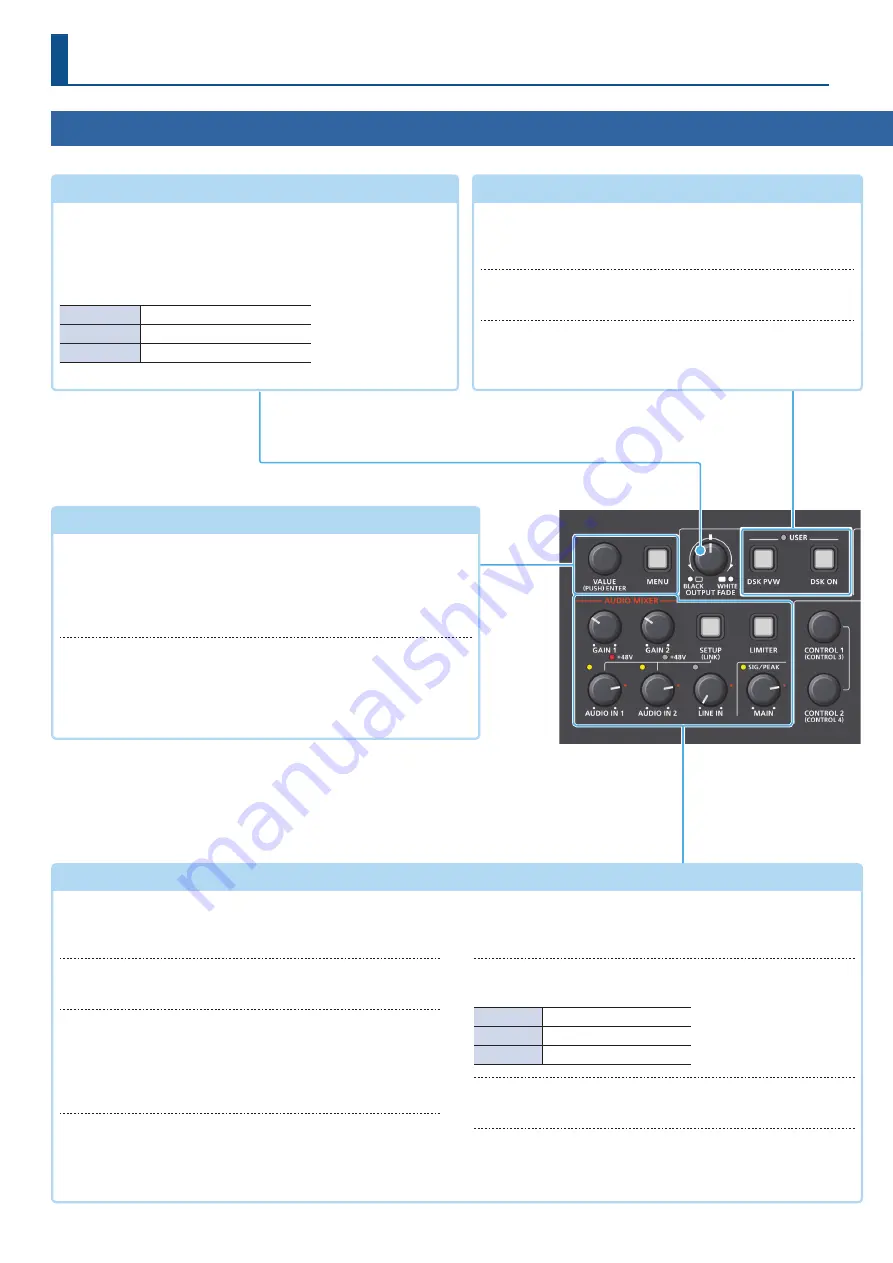
Top Panel

Panel Descriptions

Menu 

(p. 10)

[MENU] button

When this is on (lit), the menu appears on the display that’s 

connected to the OUTPUT 2 connector.
If you’re in a lower level, this button returns to the next higher level. If 

the highest menu level is shown, this button closes the menu.

[VALUE] knob

Selects a menu item, or edits the value of a setting.
Press this knob to confirm the menu item you selected or the value 

that you edited.

[OUTPUT FADE] knob 

(p. 23)

The final output video and audio fade in/out.
Rotating the knob counterclockwise fades to black, and rotating 

the knob clockwise fades to white.
The indicators located at the left and right of the [OUTPUT FADE] 

knob show the status.

Blinking red

Fading in/out

Lit red

Fade-out completed

Unlit

Normal output

AUDIO MIXER

[GAIN 1] [GAIN 2] knobs

Adjusts the input gain (sensitivity) of AUDIO IN 1 or AUDIO IN 2 

(p. 32).

+48V indicators 

(AUDIO IN 1, 2)

This is lit when phantom power is on.

[SETUP] button

Accesses the AUDIO INPUT menu. 
Long-press this button to turn the stereo link function on/off 

(p. 32). When this is on (lit), AUDIO IN 1 and 2 are linked, and 

operate as a stereo channel.

[AUDIO IN 1] [AUDIO IN 2] [LINE IN] knobs

Adjust the volume of the AUDIO IN 1, AUDIO IN 2, or LINE IN 

(p. 33).

SIG/PEAK indicators 

(AUDIO IN 1, 2/LINE IN)

These are lit green or yellow when audio input is detected. If the 

input is excessive, the indicator is lit red (p. 32).

SIG/PEAK indicator 

(MAIN)

Indicates the overall volume level.

Lit red

Volume is excessive.

Lit yellow

Volume is appropriate.

Lit green

Volume is insufficient.

[MAIN] knob

Adjusts the overall volume (p. 33).

[LIMITER] button

Turns the limiter (clipping prevention) on/off. When turned on, 

the [LIMITER] button is lit green.

USER 

(p. 29, 30)

[DSK PVW] button

When this is on (lit), it makes the DSK compositing results the 

preview output.

[DSK ON] button

Turns on/off DSK composition.

*  The settings described above are the factory defaults. You can 

also assign different functions to each button (p. 41). If a different 
function is assigned, the USER indicator is lit.

Содержание V-1HD+

Страница 1: ...01 Reference Manual 2020 Roland Corporation ...

Страница 2: ...egistered trademark or trademark of Roland Corporation in the United States and or other countries 5 5 Company names and product names appearing in this document are registered trademarks or trademarks of their respective owners ...

Страница 3: ...ediately 25 Checking the Composited Result for Final Output 26 Making Detailed Settings for the Inset Screen 27 Key Compositing the Inset Screen 28 Compositing Video with Downstream Keyer DSK 29 Compositing a Logo or Image Luminance Key 29 Compositing a Subject and Background Chroma Key 30 Audio Operations 32 Adjusting the Input Gain Sensitivity 32 Adjusting the Volume Balance 33 Applying Effects ...

Страница 4: ...hen phantom power is on SETUP button Accesses the AUDIO INPUT menu Long press this button to turn the stereo link function on off p 32 When this is on lit AUDIO IN 1 and 2 are linked and operate as a stereo channel AUDIO IN 1 AUDIO IN 2 LINE IN knobs Adjust the volume of the AUDIO IN 1 AUDIO IN 2 or LINE IN p 33 SIG PEAK indicators AUDIO IN 1 2 LINE IN These are lit green or yellow when audio inpu...

Страница 5: ...ITION V CONTROL 3 CENTER POSITION SIZE CONTROL 4 SPLIT TYPE ZOOM CUT AUTO buttons p 14 15 17 Automatically switch between the videos being input to bus A PGM and B PST and send them to the final output CUT The video switches instantly AUTO The video switches with a transition effect applied HDCP indicator p 13 This indicator is lit blinking or unlit according to the HDCP copy protection setting an...

Страница 6: ...Cord hook TALLY connector p 67 This outputs a tally signal Connect devices provided with a tally light feature POWER switch p 10 Turns the power on off RS 232 connector p 61 You can connect this to a computer equipped with an RS 232 connector and remotely control this unit Ground terminal Connect this to an external earth or ground if necessary USB MEMORY port p 20 40 Connect a USB flash drive to ...

Страница 7: ...e the SETUP button0 AUDIO IN 1 or AUDIO IN 2 0set PHANTOM 48V to ON When this is on the 48V indicator is lit NOTE If you don t need phantom power be sure to turn phantom power off You risk causing damage if you mistakenly supply phantom power to dynamic microphones audio playback devices or other devices that don t require such power These output the results of audio mixing Connect an audio record...

Страница 8: ...in Power settings If you re using a Plug in Power type mic turn plug in power on Use the SETUP button0 MIC AUX IN 0set PLUG IN POWER to ON NOTE When connecting a dynamic mic or a mic that does not support Plug in Power be sure to turn Plug in Power off If Plug in Power is on when such a mic is connected malfunctions will occur PHONES Q jack Connect headphones MIC AUX IN knob p 33 Adjusts the volum...

Страница 9: ...EC indicator If a camera that supports the REC status function is connected this is shown when the camera s REC button is pressed 2 PinP indicator Shows that this has been selected as a video source for PinP compositing 5 Still images section Shows the loaded still images p 20 21 Yellow PinP indicator Shows that this has been selected as a video source for PinP compositing Red STILL indicator Show...

Страница 10: ...2 connector 1 Press the MENU button to display the menu The menu is organized into functions 2 Turn the VALUE knob to select the menu item that you want to edit and press the VALUE knob to confirm 3 Repeat step 2 as needed Pressing the MENU button moves you back one level higher 4 Turn the VALUE knob to change the setting value and then press the VALUE knob to confirm 5 By turning the VALUE knob w...

Страница 11: ...a malfunction About frame rate The frame rates 59 94 Hz and 50 Hz are supported for input and output video To make this setting use the MENU button0 SYSTEM 0 FRAME RATE SettingtheInputFormatfortheINPUT4Connector With the factory settings the EDID assignment for the INPUT 4 connector is INTERNAL set so that EDID values of all inputtable formats are sent To specify an input format of your choice cha...

Страница 12: ...re s how to adjust the quality of the input video signals For the INPUT 4 connector you can also adjust the scaling 1 MENU button0 VIDEO INPUT 0select INPUT 1 OUTPUT 4 SCALER and press the VALUE knob 2 Use the VALUE knob to select a menu item and press the VALUE knob INPUT 1 3 INPUT 4 SCALER Menu item Explanation INPUT STATUS Displays information about the incoming video INPUT ASSIGN Selects the v...

Страница 13: ...ted HDCP video or audio connect a device that supports HDCP What s HDCP HDCP is copyright protection technology that prevents unlawful copying of content by encoding the path when sending digital signals from a video playback device to a display monitor or other display equipment 1 MENU button0 SYSTEM 0select HDCP and press the VALUE knob 2 Use the VALUE knob to select ON and press the VALUE knob ...

Страница 14: ...nd press the VALUE knob 2 Turn the VALUE knob to select A B or PGM PST 3 Press the MENU button several times to close the menu Switching in the A B Mode Here are the steps when selecting A B mode in the operation mode settings For more details on the operation modes see Setting the Operation Mode on this page 1 Slide the video fader all the way to the top or bottom The video of the bus toward whic...

Страница 15: ...e video fader If you operate the video fader in this state the output does not change until the position of the video fader matches the actual output Switching in the PGM PST Mode Here are the steps when selecting PGM PST mode in the operation mode settings For more details on the operation modes see Setting the Operation Mode p 14 1 Slide the video fader all the way to the top or bottom The video...

Страница 16: ...by which the mix wipe occurs and the direction of the wipe 1 MENU button0select MIX WIPE and press the VALUE knob 2 Use the VALUE knob to select a menu item and press the VALUE knob Menu item Explanation MIX TYPE Specifies the transition pattern for mix WIPE TYPE Specifies the transition pattern for wipe WIPE DIRECTION Specifies the direction of wipe WIPE BORDER COLOR Specifies the color of the bo...

Страница 17: ...switches to the video of the A PGM bus as a cut HCUTI Switches the video between A PGM bus and B PST bus as a cut HTRANSFORM When the video of the B PST bus is selected switches to the video of the A PGM bus as a cut only while you re holding down the button AUTO SW ASSIGN AUTO TAKEI When the video of the A PGM bus is selected switches to the video of the B PST bus HAUTOTAKEI Switches the video be...

Страница 18: ...mory Preset memories in which no settings have been saved are skipped Switching in synchronization with the BPM BPM sync This automatically switches the video at specified BPM intervals This lets you create video transitions that are synchronized with the music for example when live streaming a DJ performance or a musical performance TurningtheAutoSwitchingFunctionOn Off 1 MENU button0select AUTO ...

Страница 19: ...0 AUTO SWITCHING 0select TYPE and press the VALUE knob 2 Use the VALUE knob to select BPM SYNC and press the VALUE knob 3 Use the VALUE knob to select a menu item and press the VALUE knob Menu item Explanation BPM Specifies the BPM MODE Specifies how the video is switched TRANSITION The video switches using the currently selected transition effect mix or wipe CUT The video switches as a cut SPEED ...

Страница 20: ...mat Windows Bitmap file bmp 24 bit color uncompressed PNG file png 24 bit color Alpha channel is not supported Resolution Maximum 1920 x 1080 pixels File name No more than 28 single byte alphanumeric characters The extension bmp or png must be added Loading a still image 1 Save the still image in the root directory of the USB flash drive 2 Connect the USB flash drive containing the still image to ...

Страница 21: ...ailable 4 Press the MENU button several times to close the menu MEMO 5 Depending on the format of the input video completion of still image capture might take some time 5 If you capture when HDCP p 13 is on the still image that is created is handled in the same way as HDCP protected video It cannot be used if HDCP is off 5 You can t save the captured still image to the USB flash drive Deleting a S...

Страница 22: ...and output a still image of your choice The same still image as the final output is also output to the preview 1 Load a still image into this unit as described by the following procedures Loading a Still Image from a USB Flash Drive p 20 Capturing a Still Image from Input Video p 21 2 Press the MODE button several times to select STILL IMAGE Lit red The 1 5 4 8 buttons function as still image STIL...

Страница 23: ...video fades to a black screen WHITE AUDIO Fades in out the final output video and audio simultaneously The video fades to a white screen STILL 1 4 OUTPUT The specified still image is output as a cut to final preview output Freezing the InputVideo Freeze Here s how to temporarily freeze the input video freeze function You can apply transition effects during a video freeze Setting the Operation mode...

Страница 24: ...T H This horizontally crops the center section of the video A B A B A B B A 5 Use the CONTROL 1 and CONTROL 2 knob to adjust the position of the video or boundary If you turn a knob while pressing it these knobs function as CONTROL 3 CONTROL 4 knobs Knob Explanation CONTROL 1 Adjusts the position of the video that is shown in the left or upper side CONTROL 2 Adjusts the position of the video that ...

Страница 25: ...urn the VALUE knob to select PVW PGM or PGM 3 Press the MENU button several times to close the menu Sending the Inset Screen to Final Output Immediately Here are the steps when selecting PVW PGM mode in the operation mode settings For more details on the operation modes see Setting the Operation Mode on this page 1 Press the MODE button several times to select PinP SOURCE Lit yellow The 1 5 4 8 bu...

Страница 26: ...e video to be made the background 2 Press the MODE button several times to select PinP SOURCE Lit yellow The 1 5 4 8 buttons function as the video select button HDMI 1 4 for the inset screen 3 Press a 1 5 4 8 button to select the video you want to make the inset screen Yellow Inset screen video White Video input available Unlit Video input unavailable 4 Press the PinP button to turn on the inset s...

Страница 27: ...YSTEM 0 CONTROL KNOB PRIORITY 5 The still images loaded into this unit p 20 can be used as source images for the inset screen Use the MENU button0 PinP 0and set PinP SOURCE to STILL 1 4 Long press Making Detailed Settings for the Inset Screen Detailed settings for size shape and border width etc can be made for the inset screens 1 MENU button0select PinP and press the VALUE knob 2 Use the VALUE kn...

Страница 28: ...green Background video Inset screen video 1 MENU button0 PinP 0select PinP TYPE and press the VALUE knob 2 Use the VALUE knob to select the type of PinP compositing and press the VALUE knob Value Explanation LUMINANCE WHITE KEY A combination of PinP and luminance key white Makes the white portions of the inset screen transparent and composites the image with the background LUMINANCE BLACK KEY A co...

Страница 29: ...DSK TYPE Choose LUMINANCE WHITE or LUMINANCE BLACK Value Explanation LUMINANCE WHITE Makes white portions transparent according to brightness LUMINANCE BLACK Makes black portions transparent according to brightness 7DSK LEVEL Adjusts the degree of extraction for the key 7DSK GAIN Adjusts the degree of edge blur for the key 7MIX LEVEL Adjusts the key s overall density output level 4 Use the VALUE k...

Страница 30: ... change the value Configure the settings for each menu item while checking the composited result 5 Press the MENU button several times to close the menu Compositing using DSK 1 Press the DSK ON button to turn on DSK compositing lit The composition results is sent to final output 2 To turn off DSK compositing press the DSK ON button once again Finely adjusting the key color removed color You can ma...

Страница 31: ... the preview output video 3 Use the VALUE knob to select POSITION H or POSITION V and press the VALUE knob 4 Use the VALUE knob to adjust the position of the sampling marker Menu item Explanation POSITION H Adjusts the horizontal position POSITION V Adjusts the vertical position 5 Use the VALUE knob to select SAMPLING EXECUTE and press the VALUE knob A confirmation message appears If you want to c...

Страница 32: ... on and you switch the stereo link setting on off phantom power automatically turns off Adjusting the mic position pan The left right positioning of the sound is called pan If you re using two mics to stream a performance panning the two mics to left and right will give the sound a more spacious feel To make adjustments use the SETUP button0 AUDIO IN 1 or AUDIO IN 2 0 PAN SIG PEAK indicator Indica...

Страница 33: ...ob to adjust the volume of the output When this is adjusted appropriately the SIG PEAK indicator will light yellow Level meter indication The audio level meter is shown in each section of the multi view The level meter illumination lets you check whether the volume is adjusted appropriately dB 30 20 6 0 50 Indicator Status Red Lights up at 0 dB or higher It indicates an excessive volume level Yell...

Страница 34: ...r listening 7Equalizer This is a three band equalizer It lets you adjust the volume by boosting or cutting three frequency regions 7Reverb Adds reverberation to the sound Using an Effect Preset This unit is equipped with effects that are adjusted for specific environments These are called effect presets Simply by selecting an effect preset you can easily apply an effect that s appropriate for your...

Страница 35: ...e room The larger the value the longer the reverb time 5 Use the VALUE knob to change the value of the setting 6 Press the MENU button several times to close the menu MEMO You can assign the function to the DSK PVW or DSK ON button and turn reverb on off p 41 Applying Effects to Output Audio Here s how to modify the tonal character by applying effects to the audio output You can use limiter compre...

Страница 36: ...eo INPUT 1 4 that will use the audio follow function Audio is output only when the specified input video is selected OFF The audio is always output regardless of the video selection 3 Press the MENU button several times to close the menu MEMO The level meter shown of the multi view indicates the audio follow setting The A F symbol is shown to indicate audio for which audio follow is on Checking a ...

Страница 37: ...e the VALUE knob to select ON 4 Press the MENU button several times to close the menu MEMO 5 You can assign the mute function to the DSK PVW or DSK ON button and turn it on off p 41 5 The level meter shown of the multi view indicates the mute setting The MT symbol is shown to indicate audio for which muting is on Correcting aTime Difference Between Video and Audio Delay If there is a timing discre...

Страница 38: ...re briefly illuminated in light blue and the current settings are saved in the selected preset memory MEMO 5 You can prohibit settings from being saved or initialized p 39 to protect the preset memories Use the MENU button0 PRESET MEMORY 0and set MEMORY PROTECT to ON 5 The state of the OUTPUT FADE knob and the settings shown below are not saved to preset memories AUDIO OUTPUT PHONES OUTPUT LEVEL A...

Страница 39: ...must use this unit to format it NOTE 5 A USB flash drive that was not formatted by this unit will not be recognized 5 Never turn off the power or remove the USB flash drive while the message PLEASE WAIT is shown 5 When you format a USB flash drive all data on that USB flash drive is erased If the drive contains important data back it up to your computer before you format the drive 1 Connect the US...

Страница 40: ...r location Press the VALUE knob to highlight the character at the cursor location Use the VALUE knob to change the character and press the VALUE knob 4 When you finish entering the name use the VALUE knob to select SAVE and press the VALUE knob A confirmation message appears If you want to cancel the operation press the MENU button 5 Use the VALUE knob to select YES and press the VALUE knob The se...

Страница 41: ...w output of the DSK compositing result on off FREEZE Turns the freeze function on off AUTO SWITCHING Turns the auto switching function on off BPM TAP When TYPE in the AUTO SWITCHING menu is BPM SYNC you can set the BPM according to the tempo at which you press the button The buttons flash in sync with the current BPM setting INPUT 1 4 ASSIGN The video source assigned to the specified input switche...

Страница 42: ...MO The MENU button blinks when you try to operate a locked button knob or other control Controlling an External Recorder sVideo Record Start Stop from the Unit Connect a recorder that supports REC control functionality via HDMI to control REC START STOP on the recorder from this unit For more about recorders that support the REC control function refer to the Roland website https proav roland com S...

Страница 43: ...tent any settings saved in preset memory p 38 and the still image p 20 saved in the unit will all be lost 5 Do not turn off the power while the message PLEASE WAIT is shown 1 MENU button0 SYSTEM 0select FACTORY RESET and press the VALUE knob A confirmation message appears If you want to cancel the operation press the MENU button 2 Use the VALUE knob to select YES and press the VALUE knob Factory r...

Страница 44: ...ansmitted from the unit to the source device when the unit is connected to a source device EDID contains data such as the formats that can be input to the unit resolution color space color depth and audio information Based on the EDID information that the source device receives it will output the most appropriate video format to the unit ZOOM 1 10 0 100 0 1000 0 3 Adjusts the zoom ratio SCALING TY...

Страница 45: ...planation MIX WIPE TIME 0 0 1 0 4 0sec Specifies the video transition time PinP TIME 0 0 1 0 4 0sec For PinP compositing specifies the fade in out time for the inset screen DSK TIME 0 0 1 0 4 0sec For DSK compositing specifies the fade in out time for the overlay logo or video 4 MIX WIPE Menu item Value bold text default value Explanation TRANSITION TYPE Selects the transition effect You can also ...

Страница 46: ...ove You can also adjust this by turning the CONTROL 2 knob 5 This positions the A PGM bus video to the left or upper side B CENTER 50 0 0 0 50 0 5 5 When at SPLIT V Adjusts the horizontal position of the video placed on the right You can also adjust this by turning the CONTROL 1 knob 5 5 5 When at SPLIT H Adjusts the horizontal position of the video placed below You can also adjust this by turning...

Страница 47: ... Adjusts the vertical size of the inset screen SHAPE RECTANGLE CIRCLE DIAMOND Specifies the shape of the inset screen BORDER COLOR WHITE YELLOW CYAN GREEN MAGENTA RED BLUE BLACK SOFTEDGE Specifies the color of the border for the inset screen If this is set to SOFTEDGE the edge of the inset screen is blurred BORDER WIDTH 0 1 14 Adjusts the width of the border for the inset screen VIEW Adjusts the v...

Страница 48: ...ge blur semi transmissive region for the key MIX LEVEL 0 255 Adjusts the key s overall density output level CHROMA Make detailed settings for chroma key COLOR GREEN BLUE Specifies green or blue as the key color the color to be removed If you want a color other than green or blue to turn transparent use SAMPLING MARKER to specify the key color HUE WIDTH 30 0 30 Adjusts the hue width for the key col...

Страница 49: ...justs the hue width for the key color HUE FINE 10 0 240 360 Adjusts the center position of the hue for the key color SATURATION WIDTH 10 128 0 127 Adjusts the saturation width for the key color SATURATION FINE 10 0 255 Adjusts the center position of saturation for the key color SAMPLING MARKER 10 OFF ON If this is ON a sampling marker is shown on the preview output video for you to sample detect t...

Страница 50: ...iss or other noise that is heard during periods of silence THRESHOLD 80 48 0dB Specifies the level used as the threshold for removing audio Audio below the level set here is removed RELEASE 30 500 5000ms Adjusts the length of time until the audio is fully attenuated after audio falls below the threshold COMPRESSOR OFF ON Turns the compressor on off Effect Audio that exceeds the specified threshold...

Страница 51: ...t is heard during periods of silence THRESHOLD 80 48 0dB Specifies the level used as the threshold for removing audio Audio below the level set here is removed RELEASE 30 500 5000ms Adjusts the length of time until the audio is fully attenuated after audio falls below the threshold DE ESSER OFF ON Turns the de esser on off Effect Reduces sibilant noise the sounds you hear when pronouncing s words ...

Страница 52: ...essed This reduces the difference between the maximum volume and minimum volume making the audio more comfortable for listening THRESHOLD 50 8 0dB Specifies the level used as the threshold at which the compressor is applied Compression is applied to audio that exceeds the threshold RATIO 1 00 1 1 12 1 1 25 1 1 40 1 1 60 1 1 80 1 2 00 1 2 50 1 3 20 1 4 00 1 5 60 1 8 00 1 16 0 1 INF 1 Specifies the ...

Страница 53: ...ble for listening THRESHOLD 50 8 0dB Specifies the level used as the threshold at which the compressor is applied Compression is applied to audio that exceeds the threshold RATIO 1 00 1 1 12 1 1 25 1 1 40 1 1 60 1 1 80 1 2 00 1 2 50 1 3 20 1 4 00 1 5 60 1 8 00 1 16 0 1 INF 1 Specifies the degree of compression applied to the audio The state in which no compression is applied is defined as 1 ATTACK...

Страница 54: ...FF ON Turns the compressor on off Effect Audio that exceeds the specified threshold level is compressed This reduces the difference between the maximum volume and minimum volume making the audio more comfortable for listening THRESHOLD 40 0 20 0 0 0dB Specifies the level used as the threshold at which the compressor is applied Compression is applied to audio that exceeds the threshold RATIO 1 00 1...

Страница 55: ...IZE MEMORY 1 8 Selects the preset memory to be initialized Press the VALUE knob to initialize the preset memory START UP Specifies the settings loaded at startup LAST MEMORY Restores the state that was in effect immediately before the power was turned off Last Memory feature The current settings Last Memory values are saved every 4 seconds and when you exit a menu MEMORY 1 8 Recall the settings at...

Страница 56: ...p or png must be added DELETE STILL IMAGE STILL 1 4 Selects the still images to delete Press the VALUE knob to delete the still images An internal memory in which a still image is loaded is indicated by a symbol CAPTURE IMAGE ENTER Displays the CAPTURE IMAGE screen Follow the instructions on the screen capture a still image from the input video 13 FREEZE Menu item Value bold text default value Exp...

Страница 57: ...minute If the BPM TAP function is assigned to the DSK PVW or the DSK ON button you can set the BPM according to the tempo at which you press the button The button flashes in sync with the current BPM setting MODE Specifies how the video is switched TRANSITION The video switches using the currently selected transition effect mix or wipe CUT The video switches as a cut SPEED x1 4 x1 2 x1 x2 Specifie...

Страница 58: ...s specified by the TRANSITION TIME menu item WIPE MIX TIME HAUTO TAKEI Switches the video between A PGM bus and B PST bus The transition time is specified by the TRANSITION TIME menu item WIPE MIX TIME CUTI When the video of the A PGM bus is selected switches to the video of the B PST bus as a cut HCUTI Switches the video between A PGM bus and B PST bus as a cut TRANSFORMI When the video of the A ...

Страница 59: ...and STILL 1 through 4 in order with each press of the button If there is no video input or if a still image has not been saved this is skipped STILL 1 4 OUTPUT Outputs the specified still image INPUT 1 4 MUTE Turns the mute function on off for the specified input audio AUDIO IN 1 2 MUTE LINE IN MUTE MIC AUXIN MUTE OUTPUT MUTE Turns on off the mute function for the output audio REVERB SW Turns reve...

Страница 60: ...R MARK OFF ON Specifies whether to display the label audio level meter and REC indicator in the multi view AUTO INPUT DETECT OFF ON Turns the auto input detect function on off If this is ON input is automatically detected and the video is switched when input from the final output video is interrupted AUTO OFF OFF ON Turns the Auto Off function on off If this is ON the power to the unit turns off a...

Страница 61: ...the controller an RS 232 compatible computer or other device This unit Control device N C 1 1 RXD 2 2 RXD TXD 3 3 TXD DTR 4 4 GND 5 5 GND DSR 6 6 RTS 7 7 CTS 8 8 N C 9 9 Crossover connection The connections between 4 and 6 and between 7 and 8 are inside this unit Command Format Commands are formatted using the configuration shown below Commands are all in ASCII code stx Command code Parameter Para...

Страница 62: ... the SPLIT button stxSPS ack Press the DSK ON button stxDSK ack Press the DSK PVW button stxDVW ack PinP Adjust position of inset screen stxPP1 a b ack a b 500 500 Horizontal position 500 500 Vertical position Adjust size of the inset screen stxPPS a ack a 100 10 0 1000 100 0 Adjust zoom ratio of inset screen video stxPPZ a ack a 100 100 0 400 400 0 Set the fade in out time for the inset screen st...

Страница 63: ...g press the SETUP button stereo link function on off stxLNK ack Acquire information on volume level stxQAL a stxQAL b Send command parameters a 0 INPUT 1 1 INPUT 2 2 INPUT 3 3 INPUT 4 4 AUDIO IN 1 5 AUDIO IN 2 6 LINE IN 7 MIC AUX IN 8 ALL Response command parameters a 0 b 801 100 INPUT 1 a 1 b 801 100 INPUT 2 a 2 b 801 100 INPUT 3 a 3 b 801 100 INPUT 4 a 4 b 801 100 AUDIO IN 1 a 5 b 801 100 AUDIO ...

Страница 64: ...ons a 1 b 0 INPUT 1 4 INPUT 4 PST B cross point buttons a 2 b 0 1 5 4 4 8 1 5 4 8 buttons a 3 b 0 STILL IMAGE MODE button 1 PinP SOURCE 2 MEMORY 1 4 3 MEMORY 5 8 a 4 b 0 MIX 1 WIPE TRANSITION button a 5 b 0 Off 1 On SPLIT button a 6 b 0 Off 1 On PinP button a 7 b 0 Off 1 On Preview output of the DSK compositing result a 8 b 0 Off 1 On DSK composition a 9 b 0 Off 1 On LIMITER button a 10 b 0 Off 1 ...

Страница 65: ... 800 60 Hz WXGA 1280 x 800 60 Hz SXGA 1280 x 1024 60 Hz SXGA 1280 x 1024 60 Hz FWXGA 1366 x 768 60 Hz FWXGA 1366 x 768 60 Hz SXGA 1400 x 1050 60 Hz SXGA 1400 x 1050 60 Hz UXGA 1600 x 1200 60 Hz UXGA 1600 x 1200 60 Hz WUXGA 1920 x 1200 60 Hz WUXGA 1920 x 1200 60 Hz The refresh rate is the maximum value of each resolution Conforms to CEA 861 E VESA DMT Version 1 0 Revision 11 1920 x 1200 60 Hz Reduc...

Страница 66: ...ce AUDIO OUT L R 600 Ω PHONES 10 Ω Audio Effects Delay High pass filter De esser Compressor Noise gate Equalizer Limiter Reverb Test tone output 9 Others Other Connectors USB MEMORY USB A type for USB flash drive USB USB B type for remote control RS 232 DB 9 type male for remote control TALLY DB 9 type female for TALLY output Other Functions Preset memory 8 types Panel lock function EDID emulator ...

Страница 67: ...U button and from TALLY RS 232 set TALLY to ON TALLY connector pin layout Pin assignments Tally output 5 4 3 2 1 9 8 7 6 DB 9 type female Pin No Target Trigger method Open collector 1 GND Maximum input 12 V 200 mA 2 PGM A cross point 1 button 3 PGM A cross point 2 button 4 PGM A cross point 3 button 5 PGM A cross point 4 button 6 PST B cross point 1 button 7 PST B cross point 2 button 8 PST B cros...

Страница 68: ...AY HPF GATE COMP 3 BAND EQ DELAY 3 BAND EQ COMP LIMITER TEST TONE INPUT BUS REVERB SEND REVERB SEND L R L R Audio Block Diagram SYSTEM FORMAT 1080p 1080i 720p Select by using 1 4 5 8 SW in STILL IMAGE mode or assign to OUTPUT FADE volume STILL IMAGE OUTPUT OUTPUT BUS Analog Digital METER TOP LEVEL REVERB SEND PAN MAIN MUTE METER TOP LEVEL MONO L R MONO LR MIX MUTE REVERB LEVEL METER OUTPUT FADE MA...

Отзывы: