84
Use MIDI functionality
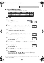
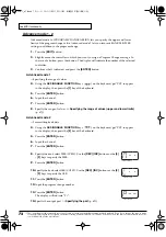
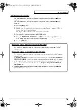
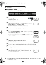
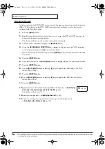
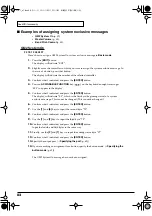
Bend Pitch Control
Since the GS Bend Pitch Control message has a
data range of 40H–58H (0–24 semitones), we will
select
Advanced mode 1
, which lets us specify
the range. Since the data format is one byte, we
will select “DT0” (p. 80) when inserting the data.
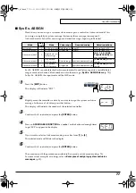
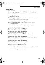
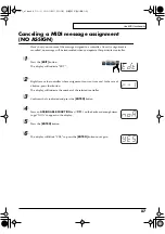
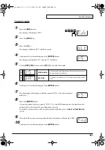
1.
Press the
[EDIT]
button.
The display will indicate “EDT”.
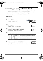
2.
Slightly move the controller to which you want
to assign the system exclusive message. In the
case of a button, press that button.
The display will indicate the number of the
selected controller.
3.
Confirm what’s indicated and press
[ENTER]
.
4.
Using the
ASSIGNABLE FUNCTION
keys
(
) on the keyboard, get "SE0" to appear in
the display, then press the
[1]
key of the
keyboard.
The display will indicate “SE1”.
5.
Confirm what’s indicated and press
[ENTER]
.
The display will blink “F0”, which is the first byte
(beginning status) of a system exclusive message.
(This cannot be changed.)
6.
Confirm what’s indicated and press
[ENTER]
.
7.
Use the
[4]
and
[1]
keys to input the second byte
“41”.
8.
Confirm what’s indicated and press
[ENTER]
.
Input the third, fourth and fifth bytes in the same
way.
9.
Since the sixth byte is the beginning of the
checksum calculation area, press the
[CHECKSUM]
key to specify this byte as the
beginning of the area for which the checksum
will be calculated.
10.
Confirm what’s indicated and press
[ENTER]
.
11.
Input the sixth byte.
12.
Since the seventh byte will have “2” in the upper
bits and the block number in the lower bits, press
[DATA]
three times.
The display will indicate “0BL”.
13.
To specify “2” for the upper bits, press the
[2]
key.
The display will indicate “2BL”.
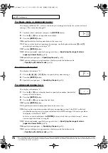
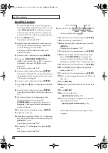
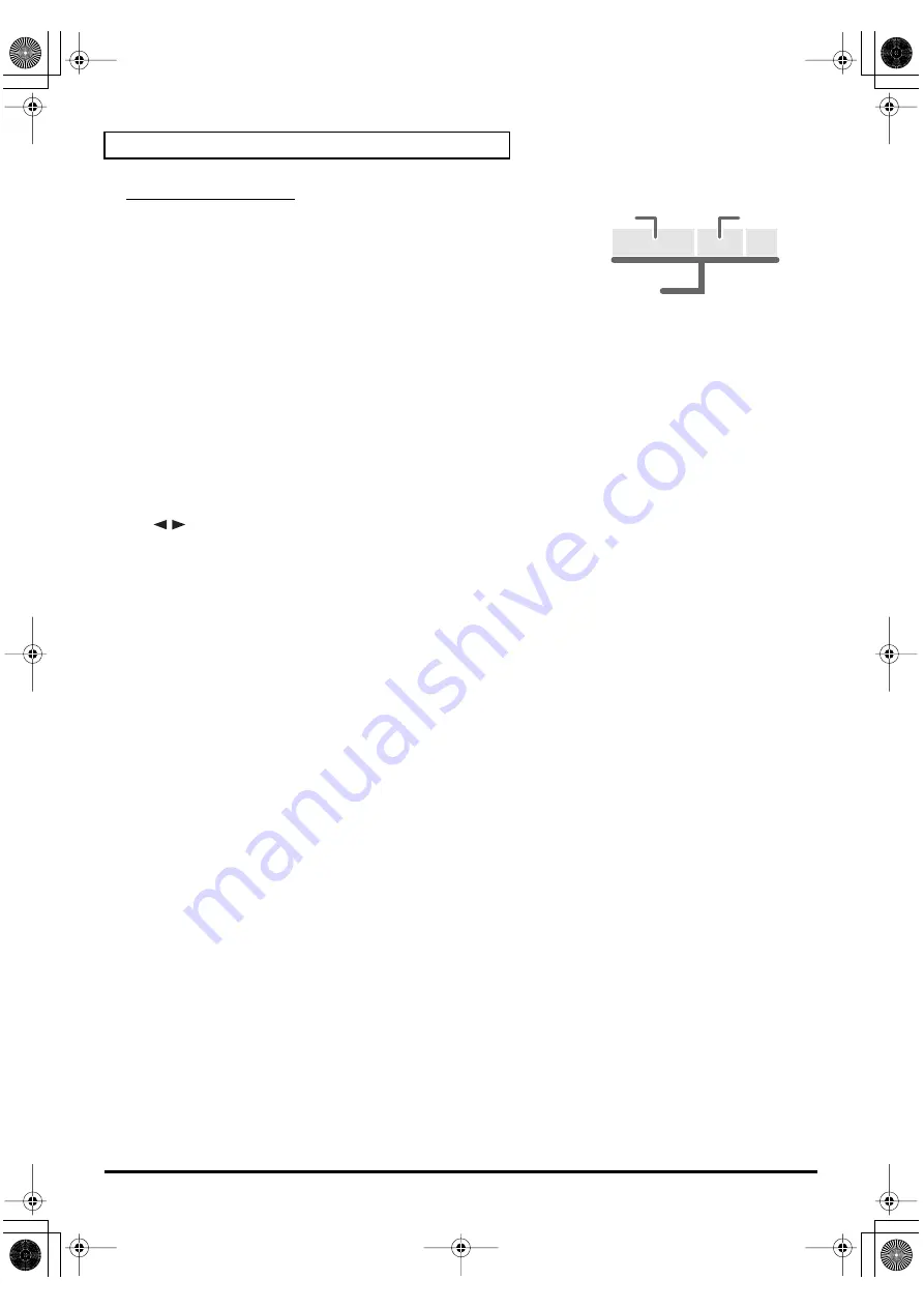
fig.checksum
14.
Confirm what’s indicated and press
[ENTER]
.
15.
In the same way, enter bytes 8.
16.
Since the ninth byte is the data area, press the
[DATA]
key.
The display will indicate “DT0.”
17.
Confirm what’s indicated and press
[ENTER]
.
18.
Since the ten byte will contain the checksum,
press the
[CHECKSUM]
key to specify the
location at which the checksum will be input.
The display will blink “CS1” (Checksum Type 1).
19.
Confirm what’s indicated and press
[ENTER]
.
20.
Press the
[F]
and then
[7]
keys to input the
ending status “F7.”
21.
Confirm what’s indicated and press
[ENTER]
.
22.
Next, specify an upper limit value of “58” for the
data area.
23.
Press
[ENTER]
.
24.
Specify a lower limit value of “40” for the data
area.
25.
Press
[ENTER]
.
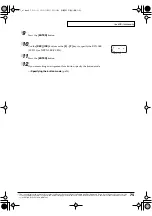
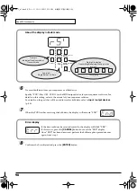
26.
Specify the output port.
(
➝
27.
If you are making an assignment for a button,
specify the button mode.
(
➝
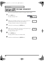
The GS Bend Pitch Control message has been
assigned.
F0 41 10 42 12 40 2x 10 DATA SUM F7
Address
Data
Checksum
Block number
1 byte
Checksum calculation region
PCR-1_e1.book 84 ページ 2003年11月20日 木曜日 午後3時22分
Содержание Edirol PCR-1
Страница 98: ...98 MEMO PCR 1_e1 book 98...


