background image


102


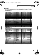
Memory sets


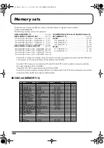
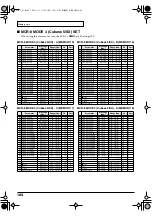
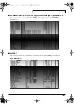
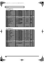
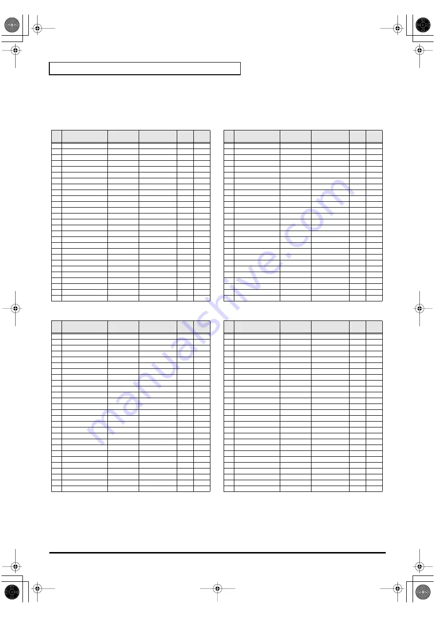
MCR-8 MODE 4 (Cubase 5/SX) SET


When using this memory set, turn the PCR-1’s 


OMNI


 (p. 54) setting OFF.


MCR-8 MODE 4 (Cubase 5/SX) - A (MEMORY: 5)

MCR-8 MODE 4 (Cubase 5/SX) - C (MEMORY: 7)

MCR-8 MODE 4 (Cubase 5/SX) - B (MEMORY: 6)

MCR-8 MODE 4 (Cubase 5/SX) - D (MEMORY: 8)


Parameter

Message 

(Hex.)

Range (Hex.)

Ch.

Port


R1

TRACK 1 PAN

CC 72(48)

0(00) - 127(7F)

16

2

R2

TRACK 2 PAN

CC 73(49)

0(00) - 127(7F)

16

2

R3

TRACK 3 PAN

CC 74(4A)

0(00) - 127(7F)

16

2

R4

TRACK 4 PAN

CC 75(4B)

0(00) - 127(7F)

16

2

R5

TRACK 5 PAN

CC 76(4C)

0(00) - 127(7F)

16

2

R6

TRACK 6 PAN

CC 77(4D)

0(00) - 127(7F)

16

2

R7

TRACK 7 PAN

CC 78(4E)

0(00) - 127(7F)

16

2

R8

TRACK 8 PAN

CC 79(4F)

0(00) - 127(7F)

16

2

S1

TRACK 1 FADER

CC 64(40)

0(00) - 127(7F)

16

2

S2

TRACK 2 FADER

CC 65(41)

0(00) - 127(7F)

16

2

S3

TRACK 3 FADER

CC 66(42)

0(00) - 127(7F)

16

2

S4

TRACK 4 FADER

CC 67(43)

0(00) - 127(7F)

16

2

S5

TRACK 5 FADER

CC 68(44)

0(00) - 127(7F)

16

2

S6

TRACK 6 FADER

CC 69(45)

0(00) - 127(7F)

16

2

S7

TRACK 7 FADER

CC 70(46)

0(00) - 127(7F)

16

2

S8

TRACK 8 FADER

CC 71(47)

0(00) - 127(7F)

16

2

B1

TRACK 1 SOLO

CC 0(00)

0(00) / 127(7F)

16

2

B2

TRACK 2 SOLO

CC 1(01)

0(00) / 127(7F)

16

2

B3

TRACK 3 SOLO

CC 2(02)

0(00) / 127(7F)

16

2

B4

TRACK 4 SOLO

CC 3(03)

0(00) / 127(7F)

16

2

B5

TRACK 5 SOLO

CC 4(04)

0(00) / 127(7F)

16

2

B6

TRACK 6 SOLO

CC 5(05)

0(00) / 127(7F)

16

2

L1

<<

CC 19(13)

0(00) / 127(7F)

16

2

L2


 Stop

CC 21(15)

0(00) / 127(7F)

16

2

L3

> Play

CC 22(16)

0(00) / 127(7F)

16

2

P1

HOLD

CC 64(40)

0(00) / 127(7F)

1

1

P2

EXPRESSION

CC 11(0B)

0(00) - 127(7F)

1

1


Parameter

Message 

(Hex.)

Range (Hex.)

Ch.

Port


R1

TRACK 9 PAN

CC 56(38)

0(00) - 127(7F)

16

2

R2

TRACK 10 PAN

CC 57(39)

0(00) - 127(7F)

16

2

R3

TRACK 11 PAN

CC 58(3A)

0(00) - 127(7F)

16

2

R4

TRACK 12 PAN

CC 59(3B)

0(00) - 127(7F)

16

2

R5

TRACK 13 PAN

CC 60(3C)

0(00) - 127(7F)

16

2

R6

TRACK 14 PAN

CC 61(3D)

0(00) - 127(7F)

16

2

R7

TRACK 15 PAN

CC 62(3E)

0(00) - 127(7F)

16

2

R8

TRACK 16 PAN

CC 63(3F)

0(00) - 127(7F)

16

2

S1

TRACK 9 FADER

CC 48(30)

0(00) - 127(7F)

16

2

S2

TRACK 10 FADER

CC 49(31)

0(00) - 127(7F)

16

2

S3

TRACK 11 FADER

CC 50(32)

0(00) - 127(7F)

16

2

S4

TRACK 12 FADER

CC 51(33)

0(00) - 127(7F)

16

2

S5

TRACK 13 FADER

CC 52(34)

0(00) - 127(7F)

16

2

S6

TRACK 14 FADER

CC 53(35)

0(00) - 127(7F)

16

2

S7

TRACK 15 FADER

CC 54(36)

0(00) - 127(7F)

16

2

S8

TRACK 16 FADER

CC 55(37)

0(00) - 127(7F)

16

2

B1

TRACK 9 SOLO

CC 32(20)

0(00) / 127(7F)

16

2

B2

TRACK 10 SOLO

CC 33(21)

0(00) / 127(7F)

16

2

B3

TRACK 11 SOLO

CC 34(22)

0(00) / 127(7F)

16

2

B4

TRACK 12 SOLO

CC 35(23)

0(00) / 127(7F)

16

2

B5

TRACK 13 SOLO

CC 36(24)

0(00) / 127(7F)

16

2

B6

TRACK 14 SOLO

CC 37(25)

0(00) / 127(7F)

16

2

L1

<<

CC 20(14)

0(00) / 127(7F)

16

2

L2


 Stop

CC 21(15)

0(00) / 127(7F)

16

2

L3

Rec

CC 23(17)

0(00) / 127(7F)

16

2

P1

HOLD

CC 64(40)

0(00) / 127(7F)

1

1

P2

EXPRESSION

CC 11(0B)

0(00) - 127(7F)

1

1


Parameter

Message 

(Hex.)

Range (Hex.)

Ch.

Port


R1

TRACK 1 PAN

CC 72(48)

0(00) - 127(7F)

16

2

R2

TRACK 2 PAN

CC 73(49)

0(00) - 127(7F)

16

2

R3

TRACK 3 PAN

CC 74(4A)

0(00) - 127(7F)

16

2

R4

TRACK 4 PAN

CC 75(4B)

0(00) - 127(7F)

16

2

R5

TRACK 5 PAN

CC 76(4C)

0(00) - 127(7F)

16

2

R6

TRACK 6 PAN

CC 77(4D)

0(00) - 127(7F)

16

2

R7

TRACK 7 PAN

CC 78(4E)

0(00) - 127(7F)

16

2

R8

TRACK 8 PAN

CC 79(4F)

0(00) - 127(7F)

16

2

S1

TRACK 1 FADER

CC 64(40)

0(00) - 127(7F)

16

2

S2

TRACK 2 FADER

CC 65(41)

0(00) - 127(7F)

16

2

S3

TRACK 3 FADER

CC 66(42)

0(00) - 127(7F)

16

2

S4

TRACK 4 FADER

CC 67(43)

0(00) - 127(7F)

16

2

S5

TRACK 5 FADER

CC 68(44)

0(00) - 127(7F)

16

2

S6

TRACK 6 FADER

CC 69(45)

0(00) - 127(7F)

16

2

S7

TRACK 7 FADER

CC 70(46)

0(00) - 127(7F)

16

2

S8

TRACK 8 FADER

CC 71(47)

0(00) - 127(7F)

16

2

B1

TRACK 1 MUTE

CC 40(28)

0(00) / 127(7F)

16

2

B2

TRACK 2 MUTE

CC 41(29)

0(00) / 127(7F)

16

2

B3

TRACK 3 MUTE

CC 42(2A)

0(00) / 127(7F)

16

2

B4

TRACK 4 MUTE

CC 43(2B)

0(00) / 127(7F)

16

2

B5

TRACK 5 MUTE

CC 44(2C)

0(00) / 127(7F)

16

2

B6

TRACK 6 MUTE

CC 45(2D)

0(00) / 127(7F)

16

2

L1

<<

CC 19(13)

0(00) / 127(7F)

16

2

L2


 Stop

CC 21(15)

0(00) / 127(7F)

16

2

L3

> Play

CC 22(16)

0(00) / 127(7F)

16

2

P1

HOLD

CC 64(40)

0(00) / 127(7F)

1

1

P2

EXPRESSION

CC 11(0B)

0(00) - 127(7F)

1

1


Parameter

Message 

(Hex.)

Range (Hex.)

Ch.

Port


R1

TRACK 9 PAN

CC 56(38)

0(00) - 127(7F)

16

2

R2

TRACK 10 PAN

CC 57(39)

0(00) - 127(7F)

16

2

R3

TRACK 11 PAN

CC 58(3A)

0(00) - 127(7F)

16

2

R4

TRACK 12 PAN

CC 59(3B)

0(00) - 127(7F)

16

2

R5

TRACK 13 PAN

CC 60(3C)

0(00) - 127(7F)

16

2

R6

TRACK 14 PAN

CC 61(3D)

0(00) - 127(7F)

16

2

R7

TRACK 15 PAN

CC 62(3E)

0(00) - 127(7F)

16

2

R8

TRACK 16 PAN

CC 63(3F)

0(00) - 127(7F)

16

2

S1

TRACK 9 FADER

CC 48(30)

0(00) - 127(7F)

16

2

S2

TRACK 10 FADER

CC 49(31)

0(00) - 127(7F)

16

2

S3

TRACK 11 FADER

CC 50(32)

0(00) - 127(7F)

16

2

S4

TRACK 12 FADER

CC 51(33)

0(00) - 127(7F)

16

2

S5

TRACK 13 FADER

CC 52(34)

0(00) - 127(7F)

16

2

S6

TRACK 14 FADER

CC 53(35)

0(00) - 127(7F)

16

2

S7

TRACK 15 FADER

CC 54(36)

0(00) - 127(7F)

16

2

S8

TRACK 16 FADER

CC 55(37)

0(00) - 127(7F)

16

2

B1

TRACK 9 MUTE

CC 88(58)

0(00) / 127(7F)

16

2

B2

TRACK 10 MUTE

CC 89(59)

0(00) / 127(7F)

16

2

B3

TRACK 11 MUTE

CC 90(5A)

0(00) / 127(7F)

16

2

B4

TRACK 12 MUTE

CC 91(5B)

0(00) / 127(7F)

16

2

B5

TRACK 13 MUTE

CC 92(5C)

0(00) / 127(7F)

16

2

B6

TRACK 14 MUTE

CC 93(5D)

0(00) / 127(7F)

16

2

L1

<<

CC 20(14)

0(00) / 127(7F)

16

2

L2


 Stop

CC 21(15)

0(00) / 127(7F)

16

2

L3

Rec

CC 23(17)

0(00) / 127(7F)

16

2

P1

HOLD

CC 64(40)

0(00) / 127(7F)

1

1

P2

EXPRESSION

CC 11(0B)

0(00) - 127(7F)

1

1

PCR-1_e1.book 102 ページ 2003年11月20日 木曜日 午後3時22分

Содержание Edirol PCR-1

Страница 1: ...aul Henri SPAAK Parc de l Esplanade F 77 462 St Thibault Lagny Cedex FRANCE TEL 01 600 73 500 FINLAND Roland Scandinavia As Filial Finland Elannontie 5 FIN 01510 Vantaa FINLAND TEL 0 9 68 24 020 GERMA...

Страница 2: ...erts the user to important instructions or warnings The specific meaning of the symbol is determined by the design contained within the triangle In the case of the symbol at left it is used for genera...

Страница 3: ...disc on a conven tional audio CD player The resulting sound may be of a level that could cause permanent hearing loss Damage to speakers or other system components may result 104 Try to prevent cords...

Страница 4: ...th 402 Never use benzine thinners alcohol or solvents of any kind to avoid the possibility of discoloration and or deformation Repairs and Data 452 Please be aware that all data contained in the unit...

Страница 5: ...ng subjected to some of the restrictions of the Serial Copy Management System SCMS This is because the unit is intended solely for musical production and is designed not to be subject to restrictions...

Страница 6: ...p Windows p 14 Macintosh p 31 Please use only the included USB cable If you require a replacement due to loss or damage please contact a EDIROL Roland Service Center listed in the Information section...

Страница 7: ...once p 60 Assign MIDI messages p 61 Note Assign p 63 Aftertouch Assign p 65 Control Change Assign p 68 Program Change Assign p 71 RPN NRPN Assign p 74 Sys Ex Assign p 77 Tempo Assign p 85 Copying a MI...

Страница 8: ...r 49 Use MIDI functionality 50 Table of operating modes 50 Startup mode 51 Features Useful When Playing 52 Setting the MIDI Transmit Channel 53 Selecting Sounds on a Sound Module Sending Program Chang...

Страница 9: ...information Press the MEMORY Button Accesses memories that are stored within the PCR 1 Press the SHIFT so it is lit and then press the MEMORY Transmits program change messages on the current channel P...

Страница 10: ...ecreases the value of a setting by one except in PLAY mode p 51 9 INC Button Increases the value of a setting by one except in PLAY mode p 51 10 HEX Button When not in PLAY mode p 51 sets the input mo...

Страница 11: ...to confirm the settings you ve made 14 OCTAVE Press OCTAVE to shift the pitch of the keyboard up or down in steps of an octave When not in PLAY mode use these buttons to return to the previous settin...

Страница 12: ...or speaker system 21 Digital output jack Headphone jack The same jack serves as both the headphone jack and digital output jack fig hint Optical These are digital jacks for connecting optical cables D...

Страница 13: ...ers Windows p 14 Getting Connected and Installing Drivers Macintosh p 31 What is a driver A driver is software that transfers data between the PCR 1 and application software running on your computer w...

Страница 14: ...tting Warn or Block Then change the setting to Ignore and click OK The installation procedure will differ depending on your system Please proceed to one of the following sections depending on the syst...

Страница 15: ...D The drive name D may be different for your system Specify the drive name of your CD ROM drive 10Use the USB cable to connect the PCR 1 to your computer Near the task bar your computer will indicate...

Страница 16: ...box will appear If What action do you want Windows to take is set to Warn A dialog box with a symbol will appear 1 Click Continue Anyway 2 Continue the installation If What action do you want Windows...

Страница 17: ...WAVE or EDIROL PCR 1 MIDI and click Next Driver installation will begin 20The Insert Disk dialog box will appear Click OK 21The Files Needed dialog box will appear Input the following into the Copy fi...

Страница 18: ...click the System icon If you changed What action do you want Windows to take If you changed the What action do you want Windows to take p 14 setting restore the original setting after Windows restart...

Страница 19: ...ntenance 3 In or pick a Control Panel icon click the System icon 2 Click the Advanced tab 3 At the right of the Performance field click Settings The Performance Options dialog box will appear 4 Click...

Страница 20: ...to Ignore make a note of the current setting Warn or Block Then change the setting to Ignore and click OK 5 Click OK to close the System Properties dialog box 6 Exit all currently running software app...

Страница 21: ...op double click the My Computer icon In the window that appears check the drive name of the CD ROM drive into which you inserted the CD ROM in step7 The drive name is the D or E displayed by the CD RO...

Страница 22: ..._XP2K 17The screen will indicate Completing the Found New Hardware Wizard Click Finish If the File signature verification Step 4 setting was not set to Ignore a Digital Signature Not Found dialog box...

Страница 23: ...to Windows as a user with administrative privileges such as Administrator 2 In the Windows desktop right click the My Computer icon and from the menu that appears select Properties The System Propert...

Страница 24: ...he Windows Start button and from the menu that appears select Settings Control Panel In Control Panel double click the System icon 2 Click the Advanced tab 3 At the right of the Performance field clic...

Страница 25: ...box will appear You are now ready to install the driver In the explanatory example shown here the drive name is given as D The drive name D may be different for your system Specify the drive name of y...

Страница 26: ...evices Properties dialog box Click OK to complete the settings Sound playback EDIROL PCR 1 Sound recording EDIROL PCR 1 Depending on how your system is set up the Sounds and Audio Devices icon may be...

Страница 27: ...ces Properties dialog box Click OK to complete the settings Sound playback EDIROL PCR 1 Sound recording EDIROL PCR 1 If the Sound and Multimedia icon is not displayed click Show all control panel opti...

Страница 28: ...ist that appears and click Apply 5 Close the Multimedia Properties dialog box Click OK to complete the settings Playback EDIROL PCR 1 Recording EDIROL PCR 1 For details on the PCR 1 s input output dev...

Страница 29: ...plication If interruptions occur in the sound repeat step 1 to step 5 and gradually increase the buffer size specified in step 2 until interruptions no longer occur Latency is the time delay from when...

Страница 30: ...ver settings dialog box In Windows XP click Switch to classic view to switch the display to the classic view EDIROL PCR 1 icon will not be displayed unless the classic view is selected In Windows Me c...

Страница 31: ...Install Click Install or Upgrade 7 The display will indicate Installing this software requires you to restart your computer when the installation is done Click Continue Installation 8 The display will...

Страница 32: ...s used for the purpose of explanation within this document this changes depending on the actual setting of the sampling frequency select on your PCR 1 p 96 Once set this way all sounds from your Macin...

Страница 33: ...successful Click Restart to restart your Macintosh OMS can be found in the OMS 2 3 8 E folder within the OMS Mac OS 9 folder of the CD ROM If you would like to know more about OMS refer to OMS_2 3_Mac...

Страница 34: ...4 If a dialog box like the one shown here appears click Turn It Off A confirmation dialog box will then appear so click OK fig 3 6_35 5 The Create a New Studio Setup dialog box will appear Click Canc...

Страница 35: ...K fig 3 10_40 8 From the File menu choose Make Current If you are unable to select Make Current it has already been applied and you may continue to the next step 9 Verify that MIDI transmission and re...

Страница 36: ...lcome to FreeMIDI will appear Click Continue 2 The FreeMIDI Preferences dialog box will appear Click Cancel 3 The About Quick Setup dialog box will appear Click Cancel This completes installation of t...

Страница 37: ...Connections to end the test 10From the File menu choose Quit to exit FreeMIDI Setup If you are unable to select Open make settings as follows 1 From the File menu choose FreeMIDI Preference 2 Uncheck...

Страница 38: ...Audio Digital Performer Metro or SPARK LE 2 Start up your ASIO compatible software 3 Open the Audio setting dialog box of your ASIO compatible software and select PCR 1 ASIO1 0 16bit as the ASIO Devi...

Страница 39: ...lication If interruptions occur in the sound repeat step 1 to step 5 and gradually increase the buffer size specified in step 2 until interruptions no longer occur Latency is the time delay from when...

Страница 40: ...ings dialog box The name of the Audio Settings dialog box and the procedure for opening the ASIO Control Panel will differ depending on your application For details refer to the operation manual for y...

Страница 41: ...elf You will need to connect it to a sound module or computer The various controllers R1 R8 S1 S8 B1 B6 L1 L3 can be assigned almost any message you want to get the control you need for your particula...

Страница 42: ...ctions If you connect as shown in the diagram you will be able to monitor the playback from your software or the sound from instruments or audio devices connected to the PCR 1 USB cable OUTPUT MD Opto...

Страница 43: ...ram refer to Input output devices p 44 For details on the actual operation refer to Use MIDI functionality p 50 USB INPUT LEVEL AUDIO INPUT AUDIO OUTPUT DIRECT MONITOR p 97 DIGITAL OUT OPTICAL PHONES...

Страница 44: ...ves audio signals sent from the PCR 1 to your computer Use this if you are us ing an application that does not have a WDM driver mode or if you want to use 24 bit audio with a non ASIO application Win...

Страница 45: ...software that receives this message will not produce a note instead it might interpret this message as meaning that the PLAY STOP button had been pressed The actual operation that will occur will depe...

Страница 46: ...96 Some connection cables contain a resistor Do not use a cable with a built in resistor to connect with the PCR 1 Doing so may make the sound extremely weak or inaudible Use the cable without a built...

Страница 47: ...n order for the sampling frequency setting to take effect you exit applications and disconnect the USB cable from the PCR 1 then connect it again If Direct Monitor p 97 is ON the signal input through...

Страница 48: ...ooped connections fig loop If the PCR 1 is connected as shown above to a device that outputs thru s the input audio such as a cassette player that is in recording mode turning on the Input monitor swi...

Страница 49: ...l that is being sent from the computer Setting the Sampling frequency Set your audio playback software the PCR 1 and your digital recording device e g MD or DAT to the same sampling frequency p 96 Whe...

Страница 50: ...urrent channel p 53 for the keyboard and bender lever Program Change mode PROGRAM CHANGE p 56 Press the SHIFT so it is lit and then press the PGM CHANGE Transmit program change messages on the current...

Страница 51: ...o add vibrato Modulation or switching the octave Octave Shift In order to send MIDI messages from the PCR 1 to your application perform the following steps 1 Set the MIDI channel the PCR 1 will use to...

Страница 52: ...sound module Modifying the Sound of Notes Modulation Pressing the Modulation Button will transmit Modulation messages changing the sound in real time usually by adding a vibrato effect MODULATION SETT...

Страница 53: ...also light according to the input mode p 54 2 Use the DEC INC buttons or the 0 F keys of the keyboard to specify the desired channel number 3 Press the ENTER button The current channel has now been se...

Страница 54: ...Keyboard Port regardless of the channel and port specified for each controller Setting the input mode fig hexdec If you are not in Play mode you can use one of two ways to input a numerical value int...

Страница 55: ...efore sending the Program Change message Program Change Mode PROGRAM CHANGE p 56 Bank mode BANK p 57 What is a bank MIDI sound modules organize their numerous sounds in various groups according to the...

Страница 56: ...that was transmitted most recently The HEX or DECIMAL button will also light according to the input mode p 54 1Use the DEC INC buttons or the 0 F keys of the keyboard to specify the program change yo...

Страница 57: ...to transmit 4 Press the ENTER button The setting will be cancelled if you press another button instead of the ENTER button fig BANK 3 5 Next specify the bank select LSB CC 32 The display will indicat...

Страница 58: ...the problem When you execute the Panic function All sound off All notes off and Reset all controllers messages will be transmitted on all channels Panic Mode PANIC fig panic2_90 fig panic 1 Simultane...

Страница 59: ...t you selected most recently 2 Use the DEC INC buttons or the 0 F keys of the keyboard to specify the memory number that you want to recall 3 Press the ENTER button The memory has now been recalled Th...

Страница 60: ...HIFT button is off R1 R8 will be transmitted When the SHIFT button is on S1 S8 will be transmitted fig MEMO This is convenient when you want to record the state of these controllers together at the be...

Страница 61: ...ERTOUCH ASSIGN p 65 CONTROL CHANGE CONTROL CHANGE ASSIGN p 68 PROGRAM CHANGE PROGRAM CHANGE ASSIGN p 71 RPN RPN NRPN ASSIGN p 74 NRPN RPN NRPN ASSIGN p 74 Sys Ex Sys Ex ASSIGN p 77 TEMPO 20 250 TEMPO...

Страница 62: ...n will remain lit while you are pressing it 1 Toggle mode The setting will alternate on off each time you press the but ton The button will light when an On message is transmitted and will go dark whe...

Страница 63: ...ENTER button The display will indicate C 6 Input the channel Use the DEC INC buttons or the 0 F keys to specify the channel fig n 7 Press the ENTER button The display will indicate N 8 Input the note...

Страница 64: ...e velocity fig p 11 Press the ENTER button The display will indicate P 12 Specify the output port Specifying the port p 62 13 If you are making an assignment for a button specify the button mode Speci...

Страница 65: ...ill indicate C 6 Input the channel Use the DEC INC buttons or the 0 F keys to specify the channel 7 Press the ENTER button 8 If you are making an assignment for a button specify the button mode Specif...

Страница 66: ...ress the ENTER button fig at1 4 Using the ASSIGNABLE FUNCTION keys on the keyboard get AT0 to appear in the display then press the 1 3 key of the keyboard The display will indicate the selected mode 5...

Страница 67: ...parameter that you are now inputting Then switch back to Decimal input mode and continue Setting the input mode p 54 fig max 1 The following display will appear 2 Use the DEC INC buttons or the 0 F k...

Страница 68: ...l Use the DEC INC buttons or the 0 F keys to specify the channel fig n 7 Press the ENTER button The display will indicate N 8 Use the DEC INC buttons or the 0 F keys to specify the control change numb...

Страница 69: ...display will indicate CC1 5 Press the ENTER button 6 Input the channel 7 Press the ENTER button 8 Input the control change number 9 Press the ENTER button fig p 10 Specify the range of values Specifyi...

Страница 70: ...play will indicate the number of the selected controller 3 Confirm what s indicated and press the ENTER button 4 Using the ASSIGNABLE FUNCTION keys on the keyboard get CC0 to appear in the display the...

Страница 71: ...the ENTER button The display will indicate N 8 Use the DEC INC buttons or the 0 F keys to specify the program change number 9 Press the ENTER button If you assign Basic mode to S1 S8 or R1 R8 moving...

Страница 72: ...imits p 67 Advanced mode 2 Transmitting bank data 4 Using the ASSIGNABLE FUNCTION keys on the keyboard get PC0 to appear in the display then press the 2 key of the keyboard 5 Press the ENTER button 6...

Страница 73: ...e keyboard 5 Press the ENTER button Program Change Decrement function PC DEC This transmits a program change that is one less than the previously transmitted program change number Program Change Incre...

Страница 74: ...PN fig c 5 Confirm what s indicated and press the ENTER button The display will blink C 6 Input the channel Use the DEC INC buttons or the 0 F keys to specify the channel 7 Press the ENTER button fig...

Страница 75: ...button specify the button mode Specifying the button mode p 62 1 Reference 1 The area displays the currently set value If it has not been set the default setting will be displayed Even if you change t...

Страница 76: ...se the DEC INC buttons or the 0 F keys to specify the channel 7 Press the ENTER button 8 Use the DEC INC buttons or the 0 F keys to specify the RPN MSB CC 101 or NRPN MSB CC 99 9 Press the ENTER butto...

Страница 77: ...s the ENTER button fig se0 4 Press an ASSIGNABLE FUNCTION key on the keyboard enough times to get SE0 to appear in the display 5 If you want to select an Advanced mode press a key from 1 to 4 The sele...

Страница 78: ...splay will indicate L 7 Use the 0 F keys of the keyboard to specify the number decimal of bytes you want to input 8 Press the ENTER button 9 Use the 0 F keys to input the first byte 10 Press the ENTER...

Страница 79: ...CHECKSUM key before you input the byte at which checksum calculation should begin The display will indicate CSS Checksum Start If you press the CHECKSUM key once again CSS Checksum Start will be canc...

Страница 80: ...changed 3 Press the ENTER button 4 If you selected DT1 through DT4 the display will indicate DT Press the ENTER button Data number Data type Default range Target of range setting Example specified upp...

Страница 81: ...ds to the channel for the sake of convenience For an actual example refer to Bend Pitch Control p 84 in the section on the Edit Mode 1 Press the DATA key several times at the location where you want t...

Страница 82: ...firm what s indicated and press the ENTER button The display will indicate F0 which is the first byte beginning status of a system exclusive message This cannot be changed This cannot be changed 6 Con...

Страница 83: ...ich is the first byte beginning status of a system exclusive message This cannot be changed 6 Confirm what s indicated and press the ENTER button 7 Use the 7 and F keys to input the second byte 7F 8 C...

Страница 84: ...s the beginning of the area for which the checksum will be calculated 10 Confirm what s indicated and press ENTER 11 Input the sixth byte 12 Since the seventh byte will have 2 in the upper bits and th...

Страница 85: ...the case of a button press that button The display will indicate the number of the selected controller fig r 1 3 Confirm what s indicated and press the ENTER button 4 Press an ASSIGNABLE FUNCTION key...

Страница 86: ...copy destination In the case of a button press that button The display will indicate the number of the selected controller 3 Confirm what s indicated and press the ENTER button fig cpy 4 Slightly mov...

Страница 87: ...splay will indicate EDT fig r 1 2 Slightly move the controller whose assignment you want to cancel In the case of a button press that button The display will indicate the number of the selected contro...

Страница 88: ...Select a memory number 1 F Use the DEC INC buttons or the 1 F keys to specify the save destination memory number The specified memory number will blink in the display 5 Confirm what s indicated and pr...

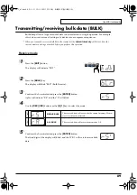
Страница 89: ...dt2 1 Press the EDIT button The display will indicate EDT fig blr 2 Press the BULK key The display will blink BLR Bulk Receive fig rs 3 Confirm what s indicated and press the ENTER button isplay will...

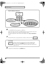
Страница 90: ...nfirm what s indicated and press the ENTER button About the display in Bulk mode fig bulk dis Transmit Receive ALL BULK SINGLE BULK 1st digit indicates Receive mode or Transmit mode receiving transmit...

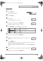
Страница 91: ...splay will blink and the PCR 1 will wait to transmit bulk data 8 Press the ENTER button On your sequencer software specify PCR 1 2 as the MIDI input device For details on this setting refer to the man...

Страница 92: ...Press the EDIT button The display will indicate EDT fig ptc 2 Press the PROTECT key The display will blink PTC 3 Confirm what s indicated and press the ENTER button 4 The display will show the current...

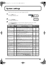
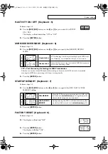
Страница 93: ...rd are to be transmitted PORT 1 p 94 H ACTIVITY ON OFF 5 Turn this ON if you are using certain applications such as Pro Tools LE When ON 90 00 7F will be output from PCR 2 approxi mately every 500 ms...

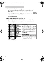
Страница 94: ...Keyboard 2 Perform steps 1 3 4 Use the DEC INC buttons or the 1 3 keys to specify F8 CLOCK PORT SET Specifying the port p 62 The specified port will indicate in the display 5 Press the ENTER button V...

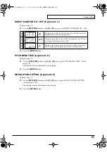
Страница 95: ...1 3 4 Use the DEC INC buttons or the 0 or 1 keys to specify the GM2 LAST ACCESS MEMORY setting 5 Press the ENTER button FACTORY RESET Keyboard 8 Perform steps 1 3 fig rst 4 The display will indicate...

Страница 96: ...to be re corded played with high quality and stable timing In Advanced mode audio signals can be transferred be tween the PCR 1 and the computer at a resolution of 24 bits and sampling frequencies of...

Страница 97: ...MODULATION SETTING Keyboard E Perform steps 1 3 4 Use the DEC INC buttons or the 0 F keys to specify MODULATION SETTING Value range 0 127 The specified value will indicate in the display 5 Press the...

Страница 98: ...98 MEMO PCR 1_e1 book 98...

Страница 99: ...contains troubleshoooting information and explanations of convenient functions You may read this material as necessary Memory sets p 100 Troubleshooting p 106 MIDI implementation p 117 Main specificat...

Страница 100: ...e PCR 1 does maintain data for P1 and P2 In order to maintain memory set compatibility with other models in the PCR series all memory sets include the data for P1 and P2 when they are bulk dumped GM2...

Страница 101: ...7 7F 1 1 P2 EXPRESSION CC 11 0B 0 00 127 7F 1 1 Parameter Message Hex Range Hex Ch Port R1 TRACK 1 1 CC 16 10 0 00 127 7F 1 2 R2 TRACK 2 1 CC 16 10 0 00 127 7F 2 2 R3 TRACK 3 1 CC 16 10 0 00 127 7F 3...

Страница 102: ...16 2 B6 TRACK 14 SOLO CC 37 25 0 00 127 7F 16 2 L1 CC 20 14 0 00 127 7F 16 2 L2 Stop CC 21 15 0 00 127 7F 16 2 L3 Rec CC 23 17 0 00 127 7F 16 2 P1 HOLD CC 64 40 0 00 127 7F 1 1 P2 EXPRESSION CC 11 0B...

Страница 103: ...2 L2 STOP B0 0F 0E B0 2F dd ON 43 OFF 03 2 L3 PLAY B0 0F 0E B0 2F dd ON 44 OFF 04 2 P1 HOLD CC 64 40 0 00 127 7F 1 1 P2 EXPRESSION CC 11 0B 0 00 127 7F 1 1 Parameter Message Hex Range Hex Ch Port R1...

Страница 104: ...T FA 2 L3 CONTINUE FB 2 P1 HOLD CC 64 40 0 00 127 7F 1 1 P2 EXPRESSION CC 11 0B 0 00 127 7F 1 1 Parameter Message Hex Range Hex Ch Port R1 DELAY MACRO F0 41 10 42 12 40 01 50 dd SUM F7 0 00 9 09 1 R2...

Страница 105: ...Y MODE F0 43 10 4C 08 0ch 05 dd F7 MONO 00 POLY 01 CURRENT CH 1 B6 XG SYSTEM ON F0 43 10 4C 00 00 7E 00 F7 1 L1 STOP FC 2 L2 START FA 2 L3 CONTINUE FB 2 P1 HOLD CC 64 40 0 00 127 7F 1 1 P2 EXPRESSION...

Страница 106: ...rive is dirty the installer may not work correctly Clean the disc and or lens using a commercially available CD cleaner or lens cleaner Are you installing the software from a networked CD ROM drive Th...

Страница 107: ...96 0 44 1kHz ADVANCE Is OMS or FreeMIDI installed Mac OS 9 The PCR 1 driver cannot be installed unless OMS or FreeMIDI are installed Please install OMS or FreeMIDI PCR 1 is not detected when making OM...

Страница 108: ...h some models of computer If this is the case connect the AC adaptor to your notebook computer The power conservation mode of your computer may limit the power that is supplied to USB Check the settin...

Страница 109: ...the driver from the beginning of the procedure p 14 Can t install delete use the driver in Windows XP 2000 Did you log on to Windows as a user with administrative privileges In order to install delet...

Страница 110: ...of your computer 3 From the Windows Start menu choose Run In the Run dialog box input the following into the Open field and click OK Windows XP 2000 users D DRIVER USB_XP2K Uninstal EXE Windows Me 98...

Страница 111: ...e may appear If this occurs click OK and exit the other applications Even if an application window is closed it is still running if it appears in the taskbar Be sure to exit unneeded applications disp...

Страница 112: ...ct PCR 1 ASIO1 0 24bit or PCR 1 ASIO2 0 24bit as the ASIO driver In this case select either PCR 1 ASIO1 0 16bit or PCR 1 ASIO2 0 16bit as the ASIO driver Graphic accelerators may cause noise to be hea...

Страница 113: ...notesare broken offprematurely or somenotes are lost within the README_E file located in the folder in which you installed the CD ROM On some computers audio playback may be interrupted due to the Po...

Страница 114: ...ted If you connect to the Internet via the internal modem port or are not connected to the Internet In the TCP IP Control Panel set Connect via to PPP After you have made the settings restart your Mac...

Страница 115: ...play 24 bit audio data Have you selected PCR 1 ASIO1 0 24bit or PCR 1 ASIO2 0 24bit as the ASIO driver fig win Recording produces a silent blank file Try setting the bit rate to 16 bit or higher If y...

Страница 116: ...vers Windows p 14 Macintosh p 31 Could the power of your equipment be off Make sure that the power to your audio equipment e g stereo and the PCR 1 has been connected Are the volume controls of the PC...

Страница 117: ...is sent Also you must leave an interval of at least 500 ms after transmitting one set of bulk dump data 2 Transmit data Channel voice messages In addition to the channel voice messages that can be tra...

Страница 118: ...mode Reset all controllers Controller number 121 Status 2nd byte 3rd byte BnH 79H 00H n MIDI channel number 0H FH Ch 1 16 Transmitted in Panic mode All notes off Controller number 123 Status 2nd byte...

Страница 119: ...e of data Data that does not have the specified starting address and data size will not be received Refer to the explanation in 3 Bulk Dump There must be an interval of at least 40 ms between each exc...

Страница 120: ...14 0EH 10 0HA Thus the nibble expressed value is 00 04 0E 0AH Example of an actual MIDI message Example1 CE 04 CnH is the Program Change status n is the MIDI channel number EH 14 and 04H 04 Thus this...

Страница 121: ...g Select Tune Request Clock Commands All Sound Off Reset All Controllers Local On Off All Notes Off Active Sensing System Reset 1 1 16 Mode 3 OMNI ON OFF MONO POLY O 9n v 1 127 O 9n v 0 O 0 127 O O O...

Страница 122: ...e phone type Digital Output connector Optical type Keyboard 25 Keys with velocity Controllers Master Volume Knob Memory Button MIDI Channel Button Shift Button Octave Shift Buttons Transpose Button As...

Страница 123: ...lk dump 89 Bulk mode 90 C CANCEL 11 50 52 Channel mode messages 118 CHANNEL PRESSURE 65 100 118 Channel voice messages 117 CHECKSUM 77 79 84 120 Continue 118 CONTROL CHANGE 61 68 69 117 CONTROL CHANGE...

Страница 124: ...de 54 Input volume 12 Insert Disk 16 17 K KEYBOARD PORT SET 93 94 L LAST ACCESS MEMORY 95 Latch mode 62 Latency 29 39 LSB 50 57 72 74 76 80 83 M Master output jacks 12 Master volume knob 9 MCR 8 MODE...

Страница 125: ...73 Program Change Increment function 73 Program Change mode 50 56 PROTECT 92 PROTECT OFF 92 PROTECT ON 92 R Receive data 117 Reset all controllers 58 118 rotary encoder 68 RPN 61 74 RPN NRPN ASSIGN 61...

Страница 126: ...ENTER Button 11 Tune request 118 U Universal non realtime system exclusive 119 Universal non realtime system exclusive message 117 Unknown device 107 USB 9 USB AUDIO MODE SETTING 93 96 USB AUDIO ON O...

Страница 127: ...erts the user to important instructions or warnings The specific meaning of the symbol is determined by the design contained within the triangle In the case of the symbol at left it is used for genera...

Страница 128: ...96 715222 MEXICO Casa Veerkamp s a de c v Av Toluca No 323 Col Olivar de los Padres 01780 Mexico D F MEXICO TEL 55 5668 6699 NICARAGUA Bansbach Instrumentos Musicales Nicaragua Altamira D Este Calle P...

Отзывы: