Unit Description
Power Supply NGMO
4.00 / 07-2004
3-7
3.4 Function
Description
3.4.1 Communication
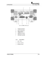
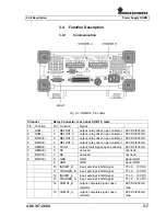
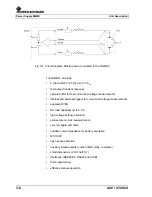
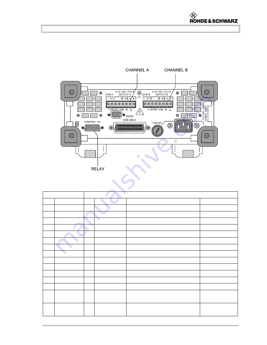
Fig. 3-3
NGMO2, Pin codes
Channel
Relay Connector, rear panel, SUB 15, male
Pin
Function
Pin Function
Signal
1
DVM-
1
RELOUT 1
output, relay driver, open collector
28 VDC/200 mA
2
DVM+
2
RELOUT 2
output, relay driver, open collector
28 VDC/200 mA
3
FORCE-
3
RELOUT 3
output, relay driver, open collector
28 VDC/200 mA
4
FORCE-
4
RELOUT 4
output, relay driver, open collector
28 VDC/200 mA
5
SENSE-
5
FAULT
output, fault signal, open collector
28 VDC/200 mA
6
SENSE+
6
NC
not used
not used
7
FORCE+
7
NC
not used
not used
8
FORCE+
8
GND
GND
signal GND
9
GND
GND
signal GND
10
INHIBIT_B
input, external inhibit signal
TTL 0 ... 12 VDC
11
TRIGGER_B
input, external inhibit signal
TTL 0 ... 12 VDC
12
INHIBIT_A
input, external inhibit signal
TTL 0 ... 12 VDC
13
TRIGGER_A
input, external inhibit signal
TTL 0 ... 12 VDC
14
COMPL_B
output, complete signal, open
collector
28 VDC/200 mA
max.
15
COMPL_A
output, complete signal, open
collector
28 VDC/200 mA
max.
Содержание NGMO1
Страница 8: ...Power Supply NGMO Tables 4 Version 4 00 07 2004 ...
Страница 14: ...Power Supply NGMO Safety 2 2 4 00 07 2004 ...
Страница 51: ...Operation Power Supply NGMO 4 00 07 2004 4 29 Fig 4 7 Status model structure ...
Страница 52: ...Power Supply NGMO Operation 4 30 4 00 07 2004 ...
Страница 56: ...Power Supply NGMO IEEE Commands 5 4 4 00 07 2004 Com mand Parameter Par value Description Def SCPI MAX DVMB ...
Страница 84: ...Power Supply NGMO Ordering Information 6 2 4 00 07 2004 ...

