Power Supply NGMO
Operation
4-16
4.00 / 07-2004
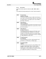
A/B25:
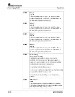
Relay 1
[on] off
Turns the output driver for relay 1 on or off. The driver
signal is applied to the “Control I/O” connector, Pin 1 on
the rear panel (ground on pin 8 and 9).
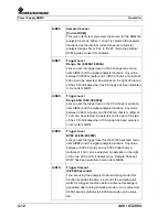
A/B26:
Relay 2
[on] off
Turns the output driver for relay 2 on or off. The driver
signal is applied to the “Control I/O” connector, Pin 2 on
the rear panel (ground on pin 8 and 9).
A/B27:
Relay 3
[on] off
Turns the output driver for relay 3 on or off. The driver
signal is applied to the “Control I/O” connector, Pin 3 on
the rear panel (ground on pin 8 and 9).
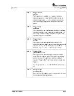
A/B28:
Relay 4
[on] off
Turns the output driver for relay 4 on or off. The driver
signal is applied to the “Control I/O” connector, Pin 4 on
the rear panel (ground on pin 8 and 9).
A/B29:
Recall setting
when power on (0-10)
The NGMO2 saves sets of settings in an internal
EEPROM. With the menu item “Recall settings when
power on” a user can select, which of the stored settings
are loaded when the device is powered up.
0: use factory defaults after power up
1 to 9: use user-defined settings, that have been previously
stored with the “SAVE” function 1 to 9.
10: use the last manual settings as the new power up
settings.
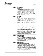
A/B30:
IEEE Address
(1-30)
This setting specifies the IEEE address of the NGMO2.
This setting is independent of the setting made with menu
item 29 (Recall setting, when power on).
Содержание NGMO1
Страница 8: ...Power Supply NGMO Tables 4 Version 4 00 07 2004 ...
Страница 14: ...Power Supply NGMO Safety 2 2 4 00 07 2004 ...
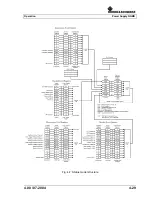
Страница 51: ...Operation Power Supply NGMO 4 00 07 2004 4 29 Fig 4 7 Status model structure ...
Страница 52: ...Power Supply NGMO Operation 4 30 4 00 07 2004 ...
Страница 56: ...Power Supply NGMO IEEE Commands 5 4 4 00 07 2004 Com mand Parameter Par value Description Def SCPI MAX DVMB ...
Страница 84: ...Power Supply NGMO Ordering Information 6 2 4 00 07 2004 ...

