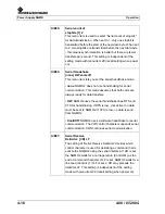
Power Supply NGMO
Operation
4-14
4.00 / 07-2004
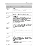
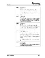
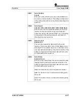
A/B16:
Sample Interval
(0.01-1000 ms)
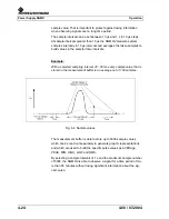
The sample interval is the time interval between two
consecutive samples used for measurement or signal
analysis. Both the “Sample length” and the “Sample
Interval” makes the total measuring time for one sample
cycle. The total time for one sample cycle is equal to the
“Sample length“ x “Sample Interval”.
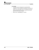
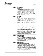
A/B17:
Sample start
[ON OFF]
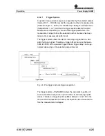
Setting the “Sample start” to ON initialises a sample or
analysis measurement. After “Sample start” has been set
to ON the sampling circuit waits for a trigger event. This
can be either an internal or external trigger. After detecting
the trigger condition, the input signal is sampled using the
given "Sample interval" (see A/B16) and the given "Sample
length" (see A/B15).
The number of times this measurement cycle is repeated is
given by the "Trigger count" (see A/B13). If "Trigger
timeout" (see (A/B10) is set to a value greater than 0 and
no trigger condition is met after "Sampling start" is set to
ON for the time specified by "Trigger timeout" the error
message "Trigger timeout" is displayed on the LCD. Both
conditions - a normal end of measurement or a "Trigger
timeout" - will reset the "Sample start" to OFF.
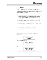
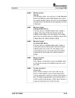
A/B18:
Read SAMP. Values
Press ENT to display
After a successful input signal measurement (sampling,
see A/B17), press the ENTER key to display the results at
the sampling points. Specific values can be selected with
the arrow keys or the rotary knob.
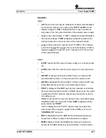
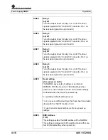
A/B19:
Meas. + Read Type
[AVER] PEAK MIN HIGH LOW RMS
The “Meas. + Read Type” menu item lets you select a
signal analysis type with the right or the left arrow key.
After selecting one of the 6 possible settings, the result can
be displayed by changing to menu item A/B20. Because all
possible analysis types are calculated internally after each
sampling cycle every setting is allowed.
Содержание NGMO1
Страница 8: ...Power Supply NGMO Tables 4 Version 4 00 07 2004 ...
Страница 14: ...Power Supply NGMO Safety 2 2 4 00 07 2004 ...
Страница 51: ...Operation Power Supply NGMO 4 00 07 2004 4 29 Fig 4 7 Status model structure ...
Страница 52: ...Power Supply NGMO Operation 4 30 4 00 07 2004 ...
Страница 56: ...Power Supply NGMO IEEE Commands 5 4 4 00 07 2004 Com mand Parameter Par value Description Def SCPI MAX DVMB ...
Страница 84: ...Power Supply NGMO Ordering Information 6 2 4 00 07 2004 ...

