9
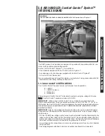
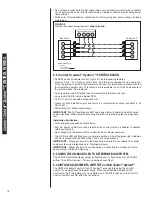
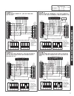
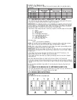
2.5 CLEARANCES
• All units are designed for “0” inches clearance to combustible material on all cabinet
surfaces.
• Units with electric heat require a one inch clearance to combustible material for the
first three feet of supply plenum and ductwork.
• Some units require a combustible floor base depending on the heating kW. The fol-
lowing table should be used to determine these requirements:
Additionally, if these units are installed down-flow, a combustible floor base is
required. See Accessories for Combustible Floor Base RXHB-XX.
Units with electric heating kW equal to or less than the values listed in the table do
not require a combustible floor base.
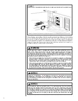
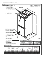
• Vertical units require clearance on at least one side of the unit for electrical connec-
tions. Horizontal units require clearance on either top or bottom for electrical connec-
tions. Refrigerant and condensate drain connections are made on the front of the unit.
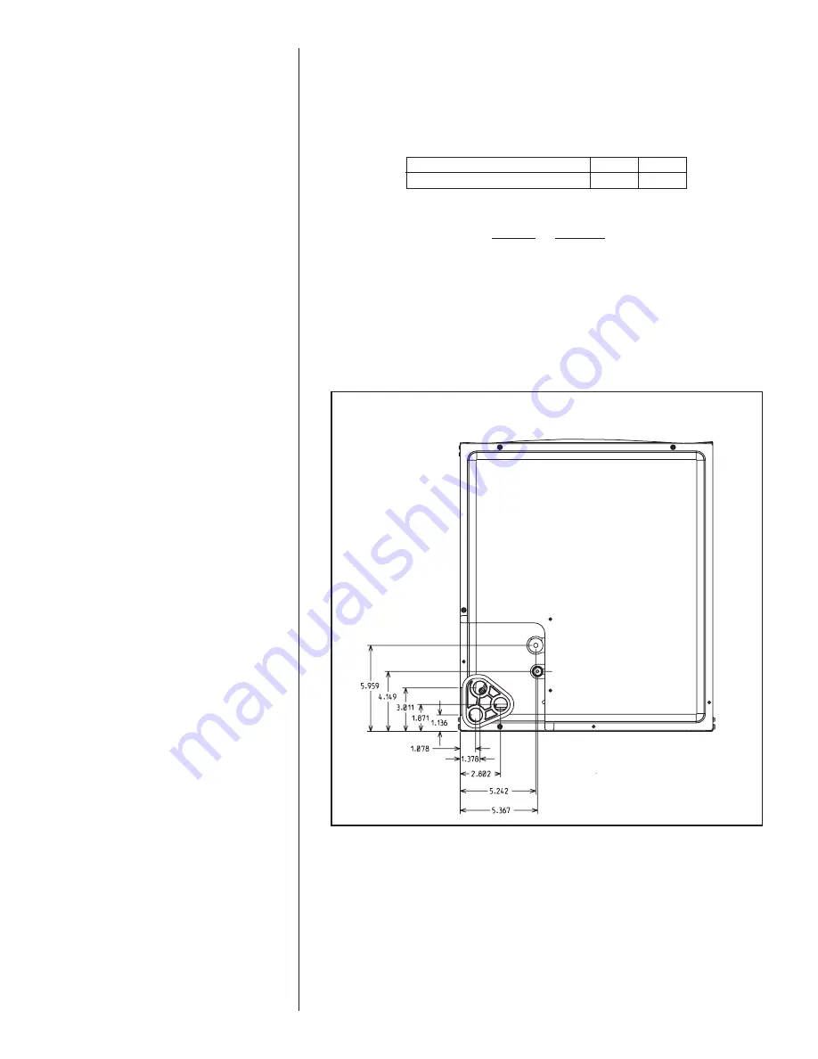
(See Figure 4.)
• All units require 24 inches maximum access to the front of the unit for service.
• These units may be installed in either ventilated or nonventilated spaces.
FIGURE 4
DIMENSIONS FOR FRONT CONNECT COIL
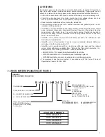
Model Cabinet Size
21
24
Maximum Model Designation kW
18
20
Содержание RHPL-HM2421JC
Страница 37: ...37 FIGURE 29 AIR HANDLER EQUIPPED WITH Serial Communication WIRING DIAGRAM...
Страница 38: ...38...
Страница 39: ...39...
Страница 40: ...40 CM 0411...


