29
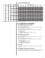
9.1 AIRFLOW PERFORMANCE DATA
10.0 SEQUENCE OF OPERATION
10.1 COOLING (cooling only or heat pump)
• In a serial communicating network:
When the thermostat “calls for cooling,” a cooling command is sent via the serial net-
work to the air handler and outdoor unit.
• Using conventional 24VAC thermostat wiring:
When the thermostat “calls for cooling,” the circuit between R and Y is completed.
A “call for cooling” causes:
1) The blower to start.
2) The compressor relay to close energizing the compressor.
3) The outdoor fan motor to start.
10.2 HEATING (electric heat only)
• In a serial communicating network:
When the thermostat “calls for heat,” a heating command is sent via the serial net-
work to the air handler.
• Using conventional 24VAC thermostat wiring:
When the thermostat “calls for heat,” the circuit between R and W is completed.
A “call for heat” causes:
1) The heater sequencer (HR1) energizes.
2) A timed delay begins.
3) The indoor blower motor (IBM) starts.
4) The heating elements (HE) energize.
10.3 DEFROST
• For sequence of operation for defrost controls, see outdoor heat pump installation
instructions.
10.4 EMERGENCY HEAT (Heating of Heat Pump)
• If selector switch on thermostat is set to the emergency heat position, the heat pump
will be locked out of the heating circuit, and all heating will be electric heat.
Size
Motor HP
Thermostat
Input
0.1
0.2
0.3
0.4
0.5
0.6
0.7
0.8
0.9
1.0
550
575
600
600
625
625
625
600
575
550
455
540
620
695
760
825
885
940
985
1030
40
55
70
85
105
120
135
150
170
185
775
775
775
800
800
825
825
825
825
825
540
615
685
750
810
870
925
975
1020
1065
70
90
115
135
160
180
205
225
250
270
875
900
900
900
900
900
900
900
900
875
570
645
715
775
835
890
945
990
1030
1070
90
110
135
155
180
200
220
240
265
285
1175
1200
1200
1200
1225
1225
1200
1200
1200
1200
700
760
820
875
925
970
1015
1055
1095
1125
180
205
235
265
290
320
345
370
400
425
1200
1175
1175
1200
1225
1225
1200
1200
1200
1200
535
595
650
700
750
800
840
880
915
950
130
160
190
220
250
280
305
335
365
390
1625
1650
1650
1650
1675
1675
1675
1650
1650
1625
635
690
745
795
840
880
915
950
980
1005
245
295
340
385
425
465
500
535
565
590
1375
1375
1375
1375
1375
1375
1375
1350
1350
1350
575
630
685
735
780
825
865
905
945
980
160
185
215
245
275
305
335
365
395
430
1650
1675
1700
1700
1700
1700
1700
1700
1700
1700
690
740
790
835
875
915
955
985
1015
1045
290
335
375
415
455
495
530
560
595
625
5-ton
Y1
Y2
230 Volts
Cabinet
Size
Nominal
Airflow
CFM
CFM
RPM
WATTS
Blower
10x8
1/3
External Static Pressure - In. W.C.
625
775
3-ton
Y1
Y2
900
1200
Nominal
Cooling
Capacity
21
21
Y1
3/4
1200
1625
1375
1675
1/2
11x11
3/4
11x11
IMPORTANT:
Observe airflow operating limits. Do not operate above 1.0 in. W.C. system external static.
2-ton
Y1
Y2
4-ton
Y2
24
24
10x8
CFM
RPM
WATTS
CFM
RPM
WATTS
CFM
RPM
WATTS
CFM
RPM
WATTS
CFM
RPM
WATTS
CFM
RPM
WATTS
CFM
RPM
WATTS
CFM
RPM
WATTS
RHPL-HM
HM2421
HM3621
HM4824
HM6024
Содержание RHPL-HM2421JC
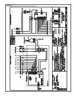
Страница 37: ...37 FIGURE 29 AIR HANDLER EQUIPPED WITH Serial Communication WIRING DIAGRAM...
Страница 38: ...38...
Страница 39: ...39...
Страница 40: ...40 CM 0411...

