22
CONVENTIONAL THERMOST
A
T WIRING
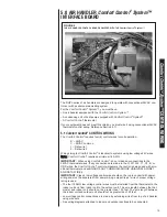
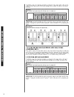
The RHPL-series of air handlers are factory configured to for proper airflow. The cooling
airflow (CAF) is fixed and the DIP switch settings have no effect on airflow. The factory
setting is:
IMPORTANT: The DIP switches are active only when using conventional a 24VAC ther-
mostat. If using the Comfort Control
2
System™, refer to Section 5.13 for adjusting air-
flows.
*5.14 COOLING AIRFLOW ADJUSTMENTS WITH SINGLE STAGE
CONDENSING UNITS
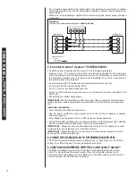
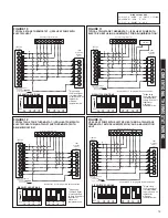
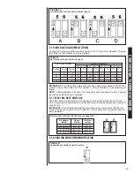
The (-)HPL- series of air handlers can be used with select single-stage condensing
units. Refer to the Engineering Specifications Sheets to determine the required airflow
for your particular combination. Refer to Table 6 to determine the air-flows available for
each (-)HPL- air handler. Reference Figures 14-17 for proper wiring of the system.
5.15 HEATING AIRFLOW ADJUSTMENT
The RHPL-series of air handlers are factory configured to for proper airflow. The heat
pump airflow (PAF) is fixed and the DIP switch settings have no effect on airflow. The
factory setting is:
IMPORTANT: The DIP switches are active only when using conventional a 24VAC ther-
mostat. If using the Comfort Control
2
System™, refer to Section 5.14 for adjusting air-
flows.
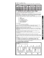
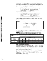
TABLE 7
AIRFLOW SETTINGS WHEN USING TRADITIONAL 24VAC THERMOSTAT
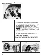
FIGURE 19
DIP SWITCH SETTING FOR HEAT PUMP AIRFLOW
9
The (-)HPL-series of air handlers are factory configured to for proper airflow. The cooling
airflow (CAF) is fixed and the DIP switch settings have no effect on airflow. The factory setting
is:
Cooling Airflow
2-ton 3-ton 4-ton 5-ton
Y1 Y2 Y1 Y2 Y1 Y2 Y1 Y2
CFM
625 775 900 1200 1200 1625 1375 1675
Table X.X – Airflow settings when using traditional 24VAC thermostat
IMPORTANT:
The DIP switches are active only when using conventional a 24VAC
thermostat. If using serial communications, refer to section 5 for adjusting airflows.
6.5 Heating Airflow Adjustment
Figure X – DIP switch setting for heat pump airflow
The (-)HPL-series of air handlers are factory configured to for proper airflow. The heat pump
airflow (PAF) is fixed and the DIP switch settings have no effect on airflow. The factory setting
is:
Heating Airflow
2-ton 3-ton 4-ton 5-ton
Y1 Y2 Y1 Y2 Y1 Y2 Y1 Y2
CFM
625 775 900 1200 1200 1625 1375 1675
Table X.X – Airflow settings when using traditional 24VAC thermostat
IMPORTANT:
The DIP switches are active only when using conventional a 24VAC
thermostat. If using serial communications, refer to section 5 for adjusting airflows.
6.6 Airflow Adjustment (TRIM)
TABLE 6
AIRFLOW SETTINGS WHEN USING TRADITIONAL 24VAC THERMOSTAT
RHPL-HM2421
RHPL-HM3621
RHPL-HM4824
RHPL-HM6024
CFM
Y1
625
775
900
1200
1200
1625
1375
1675
Y2
Y1
Y2
Y1
Y2
Y1
Y2
Cooling Airflow (also see Section 5.14)*
RHPL-HM2421
RHPL-HM3621
RHPL-HM4824
RHPL-HM6024
CFM
Y1
625
775
900
1200
1200
1625
1375
1675
Y2
Y1
Y2
Y1
Y2
Y1
Y2
Heating Airflow
Содержание RHPL-HM2421JC
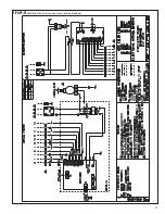
Страница 37: ...37 FIGURE 29 AIR HANDLER EQUIPPED WITH Serial Communication WIRING DIAGRAM...
Страница 38: ...38...
Страница 39: ...39...
Страница 40: ...40 CM 0411...

