
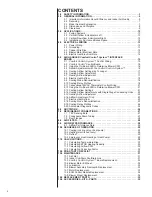


5.0 AIR HANDLER
Comfort Control
2
System™
INTERFACE BOARD
The RHPL-series of air handlers are designed to operate with conventional 24VAC con-
trols or with a serial communicating system.
For the Comfort Control
2
System™, you must have:
• An air handler equipped with the Comfort Control
2
System™
• A condensing unit or heat pump equipped with Comfort Control
2
System™
• A Comfort Control
2
thermostat
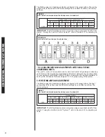
If your equipment does not meet this criteria, you must wire it using conventional 24VAC
thermostat control wiring. Reference Section 5.11.
5.1
Comfort Control
2
CONTROL WIRING
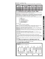
The Comfort Control
2
requires four (4) control wires for unit operation:
R – 24VAC
C – 24VAC common
1 – Data wire 1
2 – Data wire 2
Wiring sizing for Comfort Control
2
is identical to systems using low voltage 24V wires.
N
No
otte
e:: Comfort Control
2
requires a minimum 18 AWG.
IMPORTANT: When using Comfort Control
2
, do not make any connections to the
24VAC thermostat wires. If any connections are made to the G, W1, W2, Y1, Y2, B, or
ODD wires, the Comfort Control
2
control will assume the control is being used with a tra-
ditional thermostat and will IGNORE ANY COMMUNICATIONS USING DATA WIRE 1
AND DATA WIRE 2.
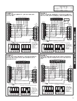
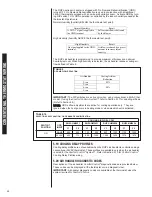
IMPORTANT: Class 2 low voltage control wire should not be run in conduit with power
wiring and must be separated from power wiring, unless Class 1 wire of proper voltage
rating is used.
• The four 18AWG low voltage control wires must be installed from the thermostat to the
indoor unit and from indoor unit to the outdoor unit. The wire length between the ther-
mostat and indoor unit should not be greater than 100 feet. The wire length between
the indoor unit and outdoor unit should not be greater than 125 feet.
• Low voltage control connections are made by extending wires from top of air handler
using wire nuts.
• See wiring diagrams attached to indoor and outdoor sections to be connected.
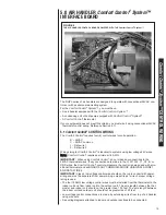
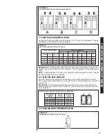
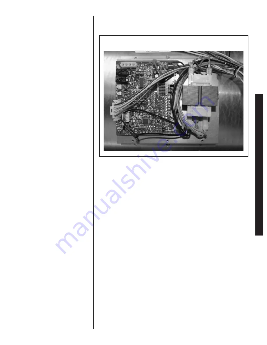
FIGURE 8
THE AIR HANDLER CONTROL BOARD EQUIPPED WITH THE Comfort Control
2
System™
15
Comfort Control
2
System™
CONTROL WIRING
Содержание RHPL-HM2421JC
Страница 37: ...37 FIGURE 29 AIR HANDLER EQUIPPED WITH Serial Communication WIRING DIAGRAM...
Страница 38: ...38...
Страница 39: ...39...
Страница 40: ...40 CM 0411...


