17
IMPORTANT: When using the Comfort Control
2
, the DIP switches have no affect on
airflow or on air handler performance.
5.5 COOLING AIRFLOW SETTINGS (BY TONNAGE)
The RHPL-series of air handlers automatically set cooling airflow when using the
Comfort Control
2
System™. The air handler detects the tonnage of the condensing
unit/heat pump and sets airflow for optimum performance and comfort. Refer to Table 2
for the airflow provided when the RHPL air handler is matched to the (-)PRL heat pump.
5.6 COOLING AIRFLOW ADJUSTMENT
The Comfort Control
2
System™ control board does allow the installer to tweak the cool-
ing a/-10% to suit the installation. When using the Comfort Control
2
System™,
the airflow can only be adjusted using the serial communicating thermostat or a service
tool. To adjust the airflow, go to the airflow adjustment menu and select the desired
adjustment. (Reference Table 2.)
IMPORTANT: Cooling airflow adjustment is accessible via the Comfort Control
2
ther-
mostat or via a service tool. Refer to their instructions to access the cooling airflow
adjustment menu.
NOTE: Cooling airflow adjustments are in effect for cooling operation only. They are
ignored when in heating mode or when electric heat is activated.
5.7 HEATING AIRFLOW ADJUSTMENT
The Comfort Control
2
control does allow the installer to tweak the heating a/-10%
to suit the installation. When using Comfort Control
2
System™, the airflow can only be
adjusted using the Comfort Control
2
thermostat or a service tool. To adjust the airflow,
go to the airflow adjustment menu and select the desired adjustment. (Reference Table 3.)
IMPORTANT: Heating airflow adjustment is accessible via the Comfort Control
2
ther-
mostat or via a service tool. Refer to their instructions to access the heating airflow
adjustment menu.
NOTE: Heating airflow adjustments are in effect for heat pump operation only. They
are ignored when in cooling mode or when electric heat is activated.
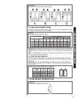
TABLE 1
RHPL AIRFLOW WHEN MATCHED TO THE (-)PRL HEAT PUMP
3
•
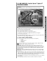
The RX Data LED will flash green in standby mode. Standby mode indicates 24VAC is
present and the data wires 1 and 2 are wired properly and there is not a command for unit
operation from the serial communicating thermostat.
IMPORTANT:
If the RX DATA LED is solid green, data wire 1 and data wire 2 are not
properly connected. Typically, the connections are switched, i.e. data wire 1 is wired to the
data wire 2 connection and data wire 2 is wired to the data wire 1 connection. Verify wiring
and correct the polarity at the two data wires.
5.3 Using the On-Board LED to Determine Blower CFM
The (-)HPL interface board LED indicates blower output by flashing one (1) second for every
100 CFM of airflow. The LED will pause 1/10 second between each flash. After the blower
CFM has been displayed, the LED will illuminate dimly for 10 seconds before repeating the
sequence. (See Table 1.)
5.4 Airflow Adjustments with Serial Communications
The (-)HPL air handler serial communicating control is configured to provide air handler
operation using serial communications or via traditional thermostat wiring. When the air handler
is wired for serial communications using Data wire 1 and Data wire 2, the DIP switches on the
serial communicating control have NO affect on the airflow.
IMPORTANT:
When using serial communications, the DIP switches have no affect or airflow
or on air handler performance.
5.5 Cooling Airflow Settings (by tonnage)
The (-)HPL-series of air handlers automatically set cooling airflow when using serial
communications. The air handler detects the tonnage of the condensing unit/heat pump and sets
airflow for optimum performance and comfort. Refer to table X.X for the airflow provided with
the (-)HPL air handler is matched to the (-)PRL heat pump.
Airflow (cfm)
Tonnage of heat
pump
2
nd
Stage
1
st
Stage
(-)PRL-024JEC 775 625
(-)PRL-036JEC 1200 875
(-)PRL-048JEC 1625 1200
(-)PRL-060JEC 1675 1375
Table X.X – (-)HPL airflow when matched to the (-)PRL heat pump.
5.6 Cooling Airflow Adjustment
The serial communicating control does allow the installer to tweak the cooling a/-10% to
suit the installation. When using serial communications, the airflow can only be adjusted using
the serial communicating thermostat or a service tool. To adjust the airflow, go to the airflow
adjustment menu and select the desired adjustment (reference table X.X).
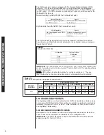
TABLE 2
AIRFLOW ADJUSTMENT SELECTION TABLE
4
Selection
None
+10%
-10%
Table X.X – Airflow Adjustment Selection Table.
IMPORTANT:
Cooling airflow adjustment is accessible via the serial communicating
thermostat or via a service tool. Refer to their instructions to access the cooling airflow
adjustment menu.
NOTE:
Cooling airflow adjustments are in effect for cooling operation only. They are ignored
when in heating mode or when electric heat is activated.
5.7 Heating Airflow Adjustment
The serial communicating control does allow the installer to tweak the heating a/-10% to
suit the installation. When using serial communications, the airflow can only be adjusted using
the serial communicating thermostat or a service tool. To adjust the airflow, go to the airflow
adjustment menu and select the desired adjustment (reference table X.X).
Selection
None
+10%
-10%
Table X.X – Airflow Adjustment Selection Table.
IMPORTANT:
Heating airflow adjustment is accessible via the serial communicating
thermostat or via a service tool. Refer to their instructions to access the heating airflow
adjustment menu.
NOTE:
Heating airflow adjustments are in effect for heat pump operation only. They are
ignored when in cooling mode or when electric heat is activated.
5.7 Electric Heat Airflow
The (-)HPL-series of air handlers are factory programmed to provide adequate airflow for
electric heat (auxiliary heat). Airflow for electric heat is fixed and cannot be field adjusted.
Electric Heat Airflow
Thermostat
Input
2-ton 3-ton 4-ton 5-ton
W1 or W2
800 CFM
1200 CFM
1600 CFM
1800 CFM
5.8 Cooling Mode Dehumidification
TABLE 3
AIRFLOW ADJUSTMENT SELECTION TABLE
4
Selection
None
+10%
-10%
Table X.X – Airflow Adjustment Selection Table.
IMPORTANT:
Cooling airflow adjustment is accessible via the serial communicating
thermostat or via a service tool. Refer to their instructions to access the cooling airflow
adjustment menu.
NOTE:
Cooling airflow adjustments are in effect for cooling operation only. They are ignored
when in heating mode or when electric heat is activated.
5.7 Heating Airflow Adjustment
The serial communicating control does allow the installer to tweak the heating a/-10% to
suit the installation. When using serial communications, the airflow can only be adjusted using
the serial communicating thermostat or a service tool. To adjust the airflow, go to the airflow
adjustment menu and select the desired adjustment (reference table X.X).
Selection
None
+10%
-10%
Table X.X – Airflow Adjustment Selection Table.
IMPORTANT:
Heating airflow adjustment is accessible via the serial communicating
thermostat or via a service tool. Refer to their instructions to access the heating airflow
adjustment menu.
NOTE:
Heating airflow adjustments are in effect for heat pump operation only. They are
ignored when in cooling mode or when electric heat is activated.
5.7 Electric Heat Airflow
The (-)HPL-series of air handlers are factory programmed to provide adequate airflow for
electric heat (auxiliary heat). Airflow for electric heat is fixed and cannot be field adjusted.
Electric Heat Airflow
Thermostat
Input
2-ton 3-ton 4-ton 5-ton
W1 or W2
800 CFM
1200 CFM
1600 CFM
1800 CFM
5.8 Cooling Mode Dehumidification
Comfort Control
2
System™
CONTROL WIRING
Содержание RHPL-HM2421JC
Страница 37: ...37 FIGURE 29 AIR HANDLER EQUIPPED WITH Serial Communication WIRING DIAGRAM...
Страница 38: ...38...
Страница 39: ...39...
Страница 40: ...40 CM 0411...

