


21
Profile D – Dry Climate profile
The Dry Climate profile is configured for areas that require little to no additional dehu-
midification.
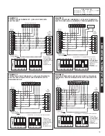
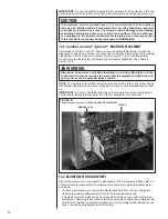
5.11 CONVENTIONAL 24VAC THERMOSTAT CONTROL WIRING
The (-)PRL series of heat pumps allow the installer to use conventional 24VAC control
wiring and a conventional thermostat for proper unit operation.
IMPORTANT: The preferred method of unit installation and operation is by the Comfort
Control
2
System™, which allows access to the fault history of the system. This diagnos-
tic information is not available when the (-)PRL unit is using a conventional thermostat.
Reference section 5.1 Comfort Control
2
System™ Control Wiring.
Thermostat control wiring requires a minimum of eight (8) wires for proper unit operation:
R – 24VAC
C – 24VAC common
G – Constant Fan
W1 – First stage electric heat
W2 – Second stage electric heat
Y1 – First stage operation
Y2 – Second stage operation
B – Heat pump operation
Optional wiring:
ODD – On demand humidification
NOTE: W1 and W2 may be jumpered together to energize all the electric heat when a
call for electric heat is received if warmer supply air temperature is desired.
NOTE: When using 24VAC thermostat control wiring, the serial communicating control
will ignore any inputs to Data wire 1 and Data wire 2.
IMPORTANT: Class 2 low voltage control wire should not be run in conduit with power
wiring and must be separated from power wiring, unless Class 1 wire of proper voltage
rating is used.
Low voltage control wiring should be 18 AWG color-coded (105°C minimum). For
lengths longer than 100 ft., 16 AWG wire should be used.
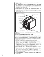
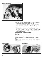
Low voltage control connections are made by extending wires from top of air handler
using wire nuts.
See wiring diagrams attached to indoor and outdoor sections to be connected
Do not leave excess field control wiring inside unit, pull excess control wire to outside of
unit and provide strain relief for field wiring on inside of cabinet at point wiring penetrates
cabinet.
Make sure, after installation, separation of control wiring and power wiring has been
maintained.
5.12 USING THE ON-BOARD LED TO DETERMINE BLOWER CFM
The CFM LED indicates blower output by flashing one (1) flash for every 100 CFM of air-
flow. The LED will pause 1/10 second between each flash.
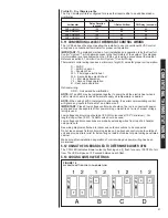
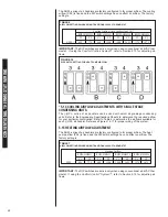
5.13 COOLING AIRFLOW SETTINGS
FIGURE 18
DIP SWITCH SETTING FOR COOLING AIRFLOW
8
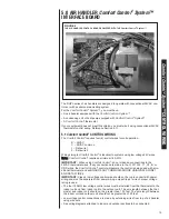
6.2 Serial Communications Control
The (-)HPL series air handler control, figure X.X, has the following features:
•
An automotive-style ATC blade fuse for transformer protection (3 amp).
•
An on-board LED to indicate blower CFM.
•
An RJ-11 port for use with a diagnostic tool.
•
Inputs for field installed supply and return air temperature sensors (available in kit RXHT-
A01)
•
DIP switches for airflow adjustments
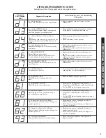
IMPORTANT:
A diagnostic tool can be used to display any air handler diagnostic codes.
However, no system changes are permitted. Any system changes MUST be done via the DIP
switches.
Installation Verification
•
24V AC power on R&C must be present at the control for the air handler to operate
•
Line voltage must be present at the control for indoor blower operation.
•
The control wires must be connected to a conventional 24VAC thermostat for proper
operation.
6.3 Using the On-Board LED to Determine Blower CFM
The (-)HPL interface board LED indicates blower output by flashing one (1) second for every
100 CFM of airflow. The LED will pause 1/10 second between each flash. After the blower
CFM has been displayed, the LED will illuminate dimly for 10 seconds before repeating the
sequence. (See Table 1.)
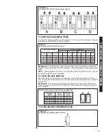
6.4 Cooling Airflow Settings
Figure X – DIP switch setting for cooling airflow
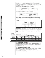
CONVENTIONAL THERMOST
A
T WIRING
On Delay
Air Handler
Delay Duration
(second)
% Rated Airflow
Off Delay (seconds)
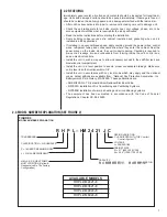
RHPL-HM2421
150
88
60
RHPL-HM3621
150
88
60
RHPL-HM4824
150
88
60
RHPL-HM6024
150
88
60
Содержание RHPL-HM2421JC
Страница 37: ...37 FIGURE 29 AIR HANDLER EQUIPPED WITH Serial Communication WIRING DIAGRAM...
Страница 38: ...38...
Страница 39: ...39...
Страница 40: ...40 CM 0411...


