


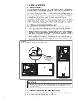


3.0 APPLICATIONS
3.1 ZONING SYSTEMS
The manufacturer does not currently provide or support zoning. However, zoning systems
can be installed with a variable speed air-handler as long as the zoning equipment manu-
facturers specifications and installation instructions are met and followed.
The preferred zoning method is to use a “bypass” system which is properly installed for
maximum efficiency. In these systems, excess air is routed back through the system to
be used again – this is opposed to a “dump” system in which excess air is routed to a
zone where it is expected that the extra heat or cooling would be least noticed.
If installed as a “bypass” system, the installation must have an optional freeze stat
installed to prevent the coil from icing with excess bypass cooling. Also, if the zoning
equipment manufacturer provides a limit switch (usually provided by the zoning manufac-
turer), this limit must be installed in the system to prevent the furnace from overheating.
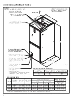
3.2 VERTICAL UPFLOW AND HORIZONTAL LEFT
The air handler unit is factory shipped for vertical upflow and horizontal left application.
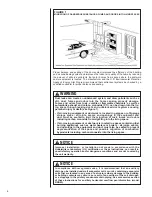
• If return air is to be ducted, install duct flush with floor. Use fireproof resilient gasket 1/8
to 1/4 in. thick between duct, unit and floor. Set unit on floor over opening.
• Support along the length of the unit, all units installed horizontally. Do not support or
suspend unit from both ends without support in the center of the cabinet. If unit is to
be supported or suspended from corners, run two reinforcing rails length of unit and
support or suspend from reinforcing rails.
• Secondary drain pan kits RXBM- are required when the unit is configured for the hori-
zontal left position over a finished ceiling and/or living space. (See Section 15.0:
Accessories - Kits - Parts.)
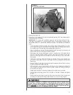
3.3 VERTICAL DOWNFLOW AND HORIZONTAL RIGHT
Conversion to Vertical Downflow/Horizontal Right: A vertical upflow unit may be con-
verted to vertical downflow/horizontal right. (See Figure 5.)
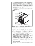
FIGURE 5
VERTICAL DOWNFLOW & HORIZONTAL RIGHT APPLICATIONS
CAUTION
Horizontal units must be configured for right hand air supply. Horizontal drain
pan must be located under indoor coil. Failure to use the drain pan can result
in property damage.
DETAIL A
ENSURE THE RETAIN-
ING CHANNEL IS FULLY
ENGAGED WITH THE
COIL RAIL.
10
Содержание RHPL-HM2421JC
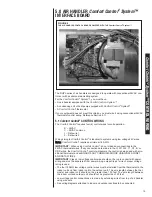
Страница 37: ...37 FIGURE 29 AIR HANDLER EQUIPPED WITH Serial Communication WIRING DIAGRAM...
Страница 38: ...38...
Страница 39: ...39...
Страница 40: ...40 CM 0411...


