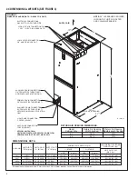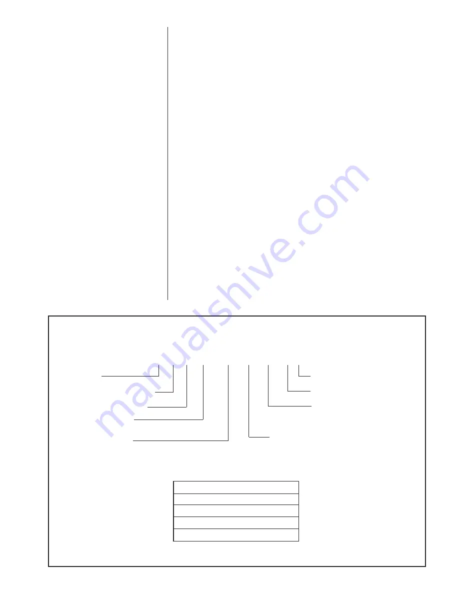
2.3 MODEL NUMBER EXPLANATION (SEE FIGURE 2)
2.2 RECEIVING
Immediately upon receipt, all cartons and contents should be inspected for transit dam-
age. Units with damaged cartons should be opened immediately. If damage is found, it
should be noted on the delivery papers, and a damage claim filed with the last carrier.
• After unit has been delivered to job site, remove carton taking care not to damage unit.
• Check the unit rating plate for unit size, electric heat, coil, voltage, phase, etc. to be
sure equipment matches what is required for the job specification.
• Read the entire instructions before starting the installation.
• Some building codes require extra cabinet insulation and gasketing when unit is
installed in attic applications.
• If installed in an unconditioned space, apply caulking around the power wires, control
wires, refrigerant tubing and condensate line where they enter the cabinet. Seal the
power wires on the inside where they exit conduit opening. Caulking is required to
pre-vent air leakage into and condensate from forming inside the unit, control box,
and on electrical controls.
• Install the unit in such a way as to allow necessary access to the coil/filter rack and
blower/control compartment.
• Install the unit in a level position to ensure proper condensate drainage. Make sure
unit is level in both directions within 1/8”.
• Install the unit in accordance with any local code which may apply and the national
codes. Latest editions are available from: “National Fire Protection Association, Inc.,
Batterysmarch Park, Quincy, MA 02269.” These publications are:
• ANSI/NFPA No. 70-(Latest Edition) National Electrical Code.
• NFPA90A Installation of Air Conditioning and Ventilating Systems.
• NFPA90B Installation of warm air heating and air conditioning systems.
• The equipment has been evaluated in accordance with the Code of Federal
Regulations, Chapter XX, Part 3280.
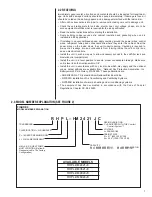
FIGURE 2
MODEL NUMBER EXPLANATION
R H P L – HM 24 21 J C
TRADEBRAND
CLASSIFICATION = AIR HANDLER
P = 16 SEER PREMIUM MODEL
L = R-410A REFRIGERANT
HM = A/C OR HEAT PUMP
MULTI-POSITION (Upflow &
Horizontal Left Is The Factory
Configuration)
DESIGN VARIATION
C = EQUIPPED WITH THE Comfort
C =
Control
2
System™
VOLTAGE
J = 208/240/1/60
CABINET SIZE
21 = 21" (600-1200 CFM)
24 = 24.5" (1200-1700 CFM)
CAPACITY
24 = 18000/24000 BTUH
48 = 42000/48000 BTUH
36 = 30000/36000 BTUH
60 = 60000 BTUH
7
AVAILABLE MODELS
RHPL-HM2421JC
RHPL-HM3621JC
RHPL-HM4824JC
RHPL-HM6024JC
Содержание RHPL-HM2421JC
Страница 37: ...37 FIGURE 29 AIR HANDLER EQUIPPED WITH Serial Communication WIRING DIAGRAM...
Страница 38: ...38...
Страница 39: ...39...
Страница 40: ...40 CM 0411...


