36
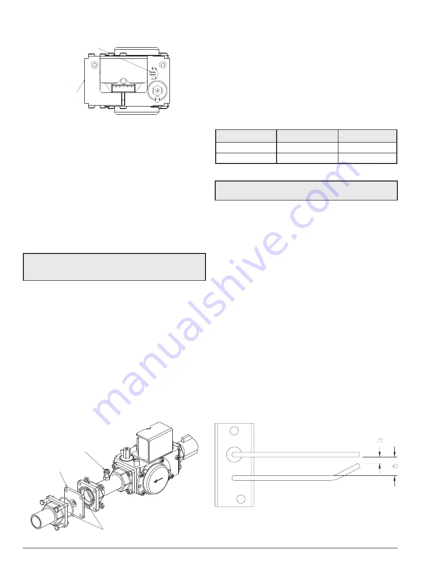
ADJUSTING SCREW
+ = MORE GAS
– = LESS GAS
GAS
INLET
F10330
Figure 41. Gas Valve
Visual Inspection
Flames can be observed through the sight glass next to the
igniter. A blue colored flame indicates normal operation.
At least every three months a visual inspection should be
made.
Electrical
Be sure that electrical service to the heater has proper
overload fuse or circuit breaker protection, wire size and
connections which comply with all applicable codes.
CAUTION:
Prior to replacing any component, make
sure that the main gas, power, and pumps are turned
OFF.
Orifice Removal
The gas orifice is located on the gas train, between the gas
valve and the combustion blower.
1.
Locate and close the external manual shutoff valve.
2.
Loosen the external gas union.
3.
Locate and remove front door panel.
4. Locate and remove the (4) bolts & nuts holding the
gas orifice in place. See the figure above.
5.
Carefully remove the gas orifice and do not misplace
the o-rings attached to the flanges.
6.
Inspect and/or replace the orifice with the correct
size.
GAS MANIFOLD
PRESSURE TAP
GAS ORIFICE
O-RING
F10347
Figure 42. Gas Train
Combustion Settings
Verify that the gas orifice matches the fuel type supplied.
The natural brass finish orifice is for natural gas and the
black oxide finish orifice is for Propane.
Table K
shows the
desired ranges for CO
2 % and limits for CO ppm. Follow
the instructions from the Adjusting Valve Manifold Pressure
section to make adjustments. Desired CO
2 % and max CO
ppm apply to all firing rates, but firing rate must be stable
for a good reading (fan RPM should not change more than
50 RPM while taking a sample).
Fuel Type
CO
2
Range (%)
CO Max (PPM)
Natural Gas
8.6 – 9.2
100
Propane
9.5 – 10.1
100
Table O. Combustion Settings
NOTE:
Orifices for propane gas have a black oxide
finish
Igniter Removal
1.
Locate and remove the top panel.
2.
Locate the igniter in front of the blower and burner.
3.
Locate and disconnect the high tension spark cable
from the igniter.
4. Using a 5/16” (8 mm) socket, remove the (2) bolts
holding the igniter down.
5. Using a flat screw driver, loosen the igniter bracket
from the combustion chamber, preferably on both
sides.
6.
Carefully remove the igniter from its location. In order
to remove the igniter without damaging the refractory,
it is necessary to rotate the igniter 90 degrees
clockwise before lifting it out of the heater.
7. When replacing or inspecting the igniter, the gap
between the ground & spark tips should be 0.15”±
0.01” (3.81± 0.25 mm). The gap between the spark
and ground rods should be uniform and the rods
should not be distorted. Inspect the ceramic insulator
at the base of the spark rod carefully for cracks,
replace the igniter if any defects are found.
Figure 43. Igniter
APPROVED
UNCONTROLLED DOCUMENT IF PRINTED
Содержание Raypak X94 SR-410
Страница 26: ...26 5 WIRING DIAGRAM APPROVED UNCONTROLLED DOCUMENT IF PRINTED...
Страница 42: ...42 Control Logic Flow Chart Pool Spa Modes APPROVED UNCONTROLLED DOCUMENT IF PRINTED...
Страница 43: ...43 10 ILLUSTRATED PARTS LIST APPROVED UNCONTROLLED DOCUMENT IF PRINTED...
Страница 51: ...51 NOTES APPROVED UNCONTROLLED DOCUMENT IF PRINTED...


