


User Manual
Reference number: 4111A-RADAR4600-GBD-R1.1
Date: 27 February 2018
Page 40 of 149
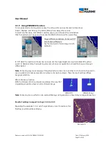
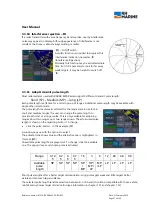
3.3.16
Set True Scaled Outline.
True Scaled Outline can be shown, if ships beam will be wider than 6mm in the selected radar range. That
depends on mechanical size of available monitor display. Anyhow it only will be available in small ranges,
may be up to 0.75NM, depending on size of ship.
To activate ‘True Scaled Outline’, click menu button [SYSTEM]. If
Menu ‘Own ship’ is not shown, click [
], to open a dropdown
window. There click ‘Own Ship’, to get before shown menu.
(Alternative, click [<] or [>] to scroll to the needed menu.)
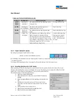
Click the box beside of <True Scaled Outline > to set a tick into.
To deactivate, click on the tick, to delete it.
To get indication of stern line and to activate the cross mark of
antenna position set a tick in regarding boxes.
Beside example shows the heading line as axis line of vessel. But
mostly one of the radar displays is installed on starboard side of
wheelhouse. Then this one always is determined as CCRP. In those
cases, the heading line will be shown shifted to the starboard side,
exactly ahead of CCRP position.
3.3.17
Reference position for Own Ship
To enable comparison between measurements made on different devices, i.e. ECDIS and RADAR, it is
important to assign a fixed point on board of ship, which will be the
'Consistent Common Reference Position' – CCRP.
From this point all radar bearing and distance measurement will have validity.
To get congruence between radar image and the optical view at the radar display position, the regarding
positions difference between radar antenna and display position must be set as distance values on an X/Y
axis. This correction is content of the installation and setting into work procedure. The installation setting
includes also the exact determination of antenna position in relation to ship's hull dimension.
The results can be checked by activating the True Scaled Outlines according to chapter 3.3.16.
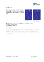
Important:
It must be taken into account, that the radar-image is seen from the position of antenna. But all
bearing and distance calculations and indications refer to the actual configured 'Reference Position'.
In case that blank sectors are set, they only can refer to the antenna-position.
If more than one display is installed, as standard always the unit installed at starboard side of bridge is
configured as reference position.
Note:
RADAR 4600 does not provide the possibility to switch the reference point from CCRP to for example
the antenna position.
3.3.18
Automatic correction for two antennas
If from conning position (CCRP) two radar antennas with different installation positions are selectable, the
specific settings of heading line and horizontal offset for each antenna, which are adjusted during
commissioning, will be automatically applied when the regarding antenna is selected.


