


19
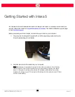
Intera 5.3
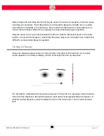
Getting to Know Sawyer
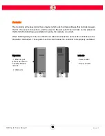
Included accessories:
•
ClickSmart Robot Side Adapter
•
Power cord
•
E-stop button and 10-foot cable
•
Landmarks #1-4 for use with Robot Positioning System.
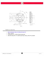
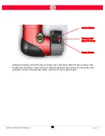
Tool Plate
The tool plate on the Sawyer robot arm is designed per the ISO 9409-1-40-4-M6 specification.
The robot tool plate has four M6 thread holes for attaching end-of-arm tooling to the robot. The
holes need to be tightened with 9 N m. If very accurate repositioning of the end-of-arm tool is
required, the Ø6 mm hole is provided for use with a pin.
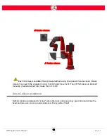
CAUTION:
•
Make sure the end-of-arm tooling is properly and securely bolted in place.
•
Make sure that the end-of-arm tool is built and configured such that it cannot
create a hazardous situation by dropping a part unexpectedly.
•
If Sawyer is equipped with vacuum grippers in the end installation, ensure that a
clean air supply is provided for connection to Sawyer’s pneumatic system and
that the maximum air pressure does not exceed 90 PSI.
Содержание Sawyer
Страница 15: ...8 Intera 5 3 Getting to Know Sawyer Hardware Overview of Your Robot ...
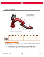
Страница 16: ...9 Intera 5 3 Getting to Know Sawyer Dimensions ...
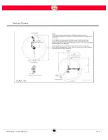
Страница 17: ...10 Intera 5 3 Getting to Know Sawyer Sawyer Reach ...
Страница 21: ...14 Intera 5 3 Getting to Know Sawyer Bottom View Inputs Power Air Input Outputs 4x Air Power and Data Video ...
Страница 93: ...86 Intera 5 3 Train Pick and Place Patterns on the Head 11 Press OK to go to the next step ...
Страница 98: ...91 Intera 5 3 Train Pick and Place Patterns on the Head 16 Press OK to allow modifications to the direction ...
Страница 104: ...97 Intera 5 3 Train Pick and Place Patterns on the Head You may now run the task ...
Страница 134: ...127 Intera 5 3 TCP IP The Set To node in the Behavior Editor is used to output information ...
Страница 138: ...131 Intera 5 3 Fieldbus Devices 3 Using a keyboard navigate to CONFIGURATION and press ENTER ...
Страница 155: ...148 Intera 5 3 ...
Страница 156: ...149 Intera 5 3 ...
Страница 175: ...168 Intera 5 3 Figure D 8 Flow chart for determining when to use 1 Figure D 4 or 2 Figures D 6 and D 7 ...
Страница 180: ...173 Intera 5 3 ...
Страница 190: ...183 Intera 5 3 Fixed Data 112 From Robot ...
Страница 191: ...184 Intera 5 3 Standard Booleans 113 To Robot 114 From Robot Standard Integers 115 To Robot 116 From Robot ...
Страница 192: ...185 Intera 5 3 Standard Floats 117 To Robot 118 From Robot Small Booleans 119 To Robot 120 From Robot ...
Страница 193: ...186 Intera 5 3 Small Integers 121 To Robot 122 From Robot Small Floats 123 To Robot 124 From Robot ...
Страница 195: ...188 Intera 5 3 Large Floats 131 To Robot 132 From Robot Large Strings 133 To Robot 134 From Robot ...
Страница 206: ...199 Intera 5 3 Small Assembly 114 From Robot 115 To Robot ...
Страница 207: ...200 Intera 5 3 Large Assembly 116 From Robot 117 To Robot ...
Страница 208: ...201 Intera 5 3 Floats 118 From Robot 119 To Robot ...
Страница 209: ...202 Intera 5 3 Strings 120 From Robot 121 To Robot ...
Страница 218: ...Z Zero G button 16 17 Zero G mode 24 Zero Gravity mode 17 zoom reset 42 ...
Страница 219: ......
Страница 220: ...Last updated June 18 2018 Intera 5 3 User Guide Getting Started Rev A ...