


120
Intera 5.3
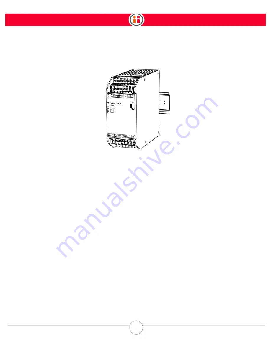
I/O Devices
•
Non-expandable SC26-2evm with analog voltage monitoring.
•
Bus Monitor input monitors redundant analog DC voltage inputs to determine if
the voltage is greater than or less than a preset level.
•
Upper and lower thresholds are independently selectable from 7 V dc to 14 V dc,
in 0.25 V dc increments.
•
Bus Monitor Input can be used in applications up to Cat 4/PLe and/or SIL3.
•
The value of the monitored voltage is accessible via the Ethernet interface.
WARNINGS
•
All safety related signals shall be constructed redundantly (i.e. two independent
channels). In order to prevent a single fault from leading to loss of a safety
function, the two channels must be kept separate.
•
Always connect safety-related signals to safety-related devices with the correct
functional safety performance level. Failure to follow this practice will result in a
compromised safety system that will not achieve the level of protection required
for the application per the risk assessment.
Содержание Sawyer
Страница 15: ...8 Intera 5 3 Getting to Know Sawyer Hardware Overview of Your Robot ...
Страница 16: ...9 Intera 5 3 Getting to Know Sawyer Dimensions ...
Страница 17: ...10 Intera 5 3 Getting to Know Sawyer Sawyer Reach ...
Страница 21: ...14 Intera 5 3 Getting to Know Sawyer Bottom View Inputs Power Air Input Outputs 4x Air Power and Data Video ...
Страница 93: ...86 Intera 5 3 Train Pick and Place Patterns on the Head 11 Press OK to go to the next step ...
Страница 98: ...91 Intera 5 3 Train Pick and Place Patterns on the Head 16 Press OK to allow modifications to the direction ...
Страница 104: ...97 Intera 5 3 Train Pick and Place Patterns on the Head You may now run the task ...
Страница 134: ...127 Intera 5 3 TCP IP The Set To node in the Behavior Editor is used to output information ...
Страница 138: ...131 Intera 5 3 Fieldbus Devices 3 Using a keyboard navigate to CONFIGURATION and press ENTER ...
Страница 155: ...148 Intera 5 3 ...
Страница 156: ...149 Intera 5 3 ...
Страница 175: ...168 Intera 5 3 Figure D 8 Flow chart for determining when to use 1 Figure D 4 or 2 Figures D 6 and D 7 ...
Страница 180: ...173 Intera 5 3 ...
Страница 190: ...183 Intera 5 3 Fixed Data 112 From Robot ...
Страница 191: ...184 Intera 5 3 Standard Booleans 113 To Robot 114 From Robot Standard Integers 115 To Robot 116 From Robot ...
Страница 192: ...185 Intera 5 3 Standard Floats 117 To Robot 118 From Robot Small Booleans 119 To Robot 120 From Robot ...
Страница 193: ...186 Intera 5 3 Small Integers 121 To Robot 122 From Robot Small Floats 123 To Robot 124 From Robot ...
Страница 195: ...188 Intera 5 3 Large Floats 131 To Robot 132 From Robot Large Strings 133 To Robot 134 From Robot ...
Страница 206: ...199 Intera 5 3 Small Assembly 114 From Robot 115 To Robot ...
Страница 207: ...200 Intera 5 3 Large Assembly 116 From Robot 117 To Robot ...
Страница 208: ...201 Intera 5 3 Floats 118 From Robot 119 To Robot ...
Страница 209: ...202 Intera 5 3 Strings 120 From Robot 121 To Robot ...
Страница 218: ...Z Zero G button 16 17 Zero G mode 24 Zero Gravity mode 17 zoom reset 42 ...
Страница 219: ......
Страница 220: ...Last updated June 18 2018 Intera 5 3 User Guide Getting Started Rev A ...