


110
Intera 5.3
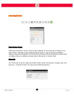
Force Sensing and Selective Arm Stiffness
Now, when you move the arm in Zero G mode, you'll see that Sawyer is constrained in its
movement along the z axis (compliant in z) relative to the end effector, and rigid along the x and y
axes.
To limit the amount of force with which Sawyer pushes, check the Force or Torque Limit box for the
appropriate axis or rotation, and enter a value. Sawyer's arm will then push no more than the
defined amount of force. A practical example of this would be training Sawyer to polish a curved
surface with no more than a certain amount of force.
In Force Mode, the endpoint exerts a directional force on objects it comes in contact with, instead
of moving to a set position. The endpoint will accelerate in the force direction until it makes contact.
The force values can be either positive or negative (push or pull).
When the actual position is the same as the target position of a given Contact node, no forces are
generated. So, if you are using stiffness and you want a force to be applied when the active end-
point is in contact with a surface, you need to change the position of the Contact node to below the
surface.
Unless the active endpoint is in contact with a surface, no forces are imparted because the
commanded and actual position are essentially the same. If you are using pure impedance mode,
you will not experience the accelerations that can occur with force mode and the arm is in free
space. Both modes have the effect of imparting force on a surface in which they come into contact,
but impedance mode is more predictable.
Содержание Sawyer
Страница 15: ...8 Intera 5 3 Getting to Know Sawyer Hardware Overview of Your Robot ...
Страница 16: ...9 Intera 5 3 Getting to Know Sawyer Dimensions ...
Страница 17: ...10 Intera 5 3 Getting to Know Sawyer Sawyer Reach ...
Страница 21: ...14 Intera 5 3 Getting to Know Sawyer Bottom View Inputs Power Air Input Outputs 4x Air Power and Data Video ...
Страница 93: ...86 Intera 5 3 Train Pick and Place Patterns on the Head 11 Press OK to go to the next step ...
Страница 98: ...91 Intera 5 3 Train Pick and Place Patterns on the Head 16 Press OK to allow modifications to the direction ...
Страница 104: ...97 Intera 5 3 Train Pick and Place Patterns on the Head You may now run the task ...
Страница 134: ...127 Intera 5 3 TCP IP The Set To node in the Behavior Editor is used to output information ...
Страница 138: ...131 Intera 5 3 Fieldbus Devices 3 Using a keyboard navigate to CONFIGURATION and press ENTER ...
Страница 155: ...148 Intera 5 3 ...
Страница 156: ...149 Intera 5 3 ...
Страница 175: ...168 Intera 5 3 Figure D 8 Flow chart for determining when to use 1 Figure D 4 or 2 Figures D 6 and D 7 ...
Страница 180: ...173 Intera 5 3 ...
Страница 190: ...183 Intera 5 3 Fixed Data 112 From Robot ...
Страница 191: ...184 Intera 5 3 Standard Booleans 113 To Robot 114 From Robot Standard Integers 115 To Robot 116 From Robot ...
Страница 192: ...185 Intera 5 3 Standard Floats 117 To Robot 118 From Robot Small Booleans 119 To Robot 120 From Robot ...
Страница 193: ...186 Intera 5 3 Small Integers 121 To Robot 122 From Robot Small Floats 123 To Robot 124 From Robot ...
Страница 195: ...188 Intera 5 3 Large Floats 131 To Robot 132 From Robot Large Strings 133 To Robot 134 From Robot ...
Страница 206: ...199 Intera 5 3 Small Assembly 114 From Robot 115 To Robot ...
Страница 207: ...200 Intera 5 3 Large Assembly 116 From Robot 117 To Robot ...
Страница 208: ...201 Intera 5 3 Floats 118 From Robot 119 To Robot ...
Страница 209: ...202 Intera 5 3 Strings 120 From Robot 121 To Robot ...
Страница 218: ...Z Zero G button 16 17 Zero G mode 24 Zero Gravity mode 17 zoom reset 42 ...
Страница 219: ......
Страница 220: ...Last updated June 18 2018 Intera 5 3 User Guide Getting Started Rev A ...