Operator Unit
130--613
Operator Unit
23
Edition: March 11, 2005
3648/130--613.DOC010102
Up
Down
GYRO 1
No Heading
Gyro 2
------.--
°
Gyro 3
------.--
°
Magnet
------.--
°
ESC
------.--
°
Aut Spd: ----.--Kts
Aut Lat: ----
°
----‘
Lamp
Test
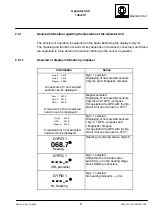
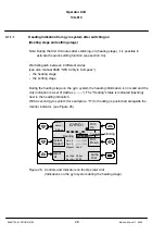
Figure 18: Controls and Indicators on the Operator Unit
(No CAN bus is connected to the Operator Unit)
2.)
All the information is faded out and replaced with horizontal dashes
(see Figure 18).
Dim
Up
Dim
Down
Alarm
Ackn
NO CONNECTION
OPERATOR
UNIT
Contrast
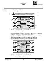
Figure 19: Controls and Indicators on the Operator Unit
(No CAN bus is connected to the Operator Unit)
3.)
The display alters after 3--5 seconds and the error message “NO CONNECTION”
is displayed. (see Figure 19).
A visual and audible alarm is emitted.
Cause of this error message can be either a missing termination resistor, a missing CAN
bus connection or a wrong connected CAN bus.
Once the “Alarm Ackn” key is pressed, the error message and the LED cease to flash.
The LED continues to light constant red and the error message stays on the display until
the fault has been remedied.
“Penel Setup” is possible.

