Operator Unit
130--613
Operator Unit
7
Edition: March 11, 2005
3648/130--613.DOC010102
2
Operation
2.1
Controls and Indicators on the Operator Unit
1
2
3
4
5
6
7
8
9
Dim
up
Dim
down
GYRO 1
068.7
°
Heading
Aut Spd: 08.5Kts
Aut Lat: 50
°
05‘
Gyro 2
067.9
°
Gyro 3
068.1
°
Magnet 069.0
°
Select
Speed
Select
Lat
Contrast
Select
Sensor
& Menu
Lamp
Test
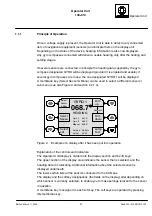
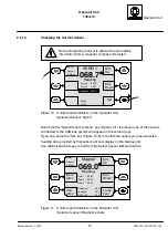
Figure 5:
Controls and Indicators on the Operator Unit
Figure 5/no.
Signification
5/1, 5/2, 5/3,
5/4, 5/5, 5/6
Membrane keys
The signification of the membrane keys is determined by Soft-
key fields (5/9).
5/4
(Red) membrane key used to acknowledge alarms and confirm
data entries.
Performing Lamp Test.
5/7
LCD display
5/8
Two-colour LED
red: alarm message
yellow. request to confirm where:
-- values have been changed
-- a sensor has been selected
Note:
If an alarm message occurs during a period of request
to confirm, then the alarm message has the higher
priority.
5/9
Soft key field
The software determines the function.


