27
120 VAC WIRING
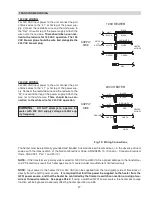
For 120 VAC input power to the unit, connect the pair
of black wires to the “L1” or hot leg of the power sup-
ply. Connect the red/white wire and the white wire to
the “Ret” or neutral leg of the power supply. Attach the
wire nut to the red wire.
There should be no connec-
tion to the red wire for 120 VAC operation. The 120
VAC blower plug should be wire tied alongside the
240 VAC blower plug.
120V HEATER
SUPPLY
SIDE
RETURN
or
NEUTRAL
HEATER
6 WIRES
L1
HOT
RED
BLACK
BLACK
BLACK
GREEN
GREEN
WHITE
WHITE
RED/WHITE
240V HEATER
HEATER
6 WIRES
GROUND
L1
L2
BLACK
BLACK
RED
RED
RED/WHITE
HOT
HOT
BLACK
GREEN
GREEN
WHITE
SUPPLY
SIDE
NOTE:
Input power to the heater (120 or 240 VAC) can be supplied from the load (pump) side of time clock or
directly from the GFCI power source.
It is required that full-time power be supplied to the heater from the
GFCI power source, and that the heater be controlled by the fireman’s switch connection or using a two-
wire or three-wire remote. See pages 38-40.
If using a switched GFCI power source, the heater post-purge
function will be bypassed, adversely affecting heater operation and life.
NOTE:
If the transformer’s primary side is wired for 120 VAC and 240 VAC is applied, damage to the transformer
and PC board may result. Such damages are not covered under manufacturer’s limited warranty.
WARNING:
DO NOT attempt to operate the
heater with 208 VAC supply voltage or 50Hz sup-
ply frequency.
240 VAC WIRING
For 240 VAC input power to the unit, connect the pair
of black wires to the “L1” or hot leg of the power sup-
ply. Connect the red/white wire and the red wire to the
“L2” or second hot leg of the power supply. Attach the
wire nut to the white wire.
There should be no con-
nection to the white wire for 240 VAC operation.
The heater must be electrically grounded and bonded in accordance with local codes, or, in the absence of local
codes, with the latest edition of the National Electrical Code, ANSI/NFPA 70. (Canada - Canadian Electrical
Code, CSA C22.1, Part 1 and Part 2.)
TRANSFORMER WIRING
Fig. 19: Wiring Connections
Содержание 259B
Страница 13: ...13 Florida Building Code Fig 6 Florida Building Code 2010 Tie Down Method...
Страница 32: ...32 WIRING DIAGRAM...
Страница 44: ...44 SECTION 6 REPLACEMENT PARTS...
Страница 48: ...www raypak com Raypak Inc 2151 Eastman Avenue Oxnard CA 93030 805 278 5300 Fax 805 278 5468 Litho in U S A 48...


