20
Horizontal Through-the-Wall Venting
(Category III)
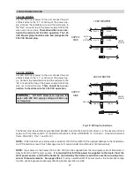
Fig 10: Horizontal Through-the-Wall Venting
Fig. 9: Vertical Venting
CAUTION:
This venting system requires the
installation of a condensate drain in the vent piping
per the vent manufacturer’s instructions. Failure to
install a condensate drain in the venting system will
void all warranties on this heater.
Installation
These installations utilize the heater’s internal blower
to vent the combustion products to the outdoors.
Combustion air is taken from inside the room and the
vent is installed horizontally through the wall to the out-
doors. Adequate combustion and ventilation air must
be supplied to the equipment room in accordance with
the NFGC (U.S.) or B149 (Canada).
The total length of the horizontal through-the-wall flue
system should not exceed 80 equivalent ft in length. If
horizontal run exceeds 80 equivalent ft, an appropri-
ately sized variable-speed extractor must be used.
Each elbow used is equal to 10 ft of straight pipe. This
will allow installation in one of the five following
arrangements:
•
80’ of straight flue pipe
•
70’ of straight flue pipe and one elbow
•
60’ of straight flue pipe and two elbows
•
50’ of straight pipe and three elbows
•
40’ of straight pipe and four elbows
The vent cap is not considered in the overall length of
the venting system.
The connection from the appliance vent to the stack
must be as direct as possible. The horizontal breach-
ing of a vent must have an upward slope of not less
than 1/4 inch per linear foot from the heater to the vent
terminal. The horizontal portions of the vent shall also
be supported for the design and weight of the material
employed to maintain clearances and to prevent phys-
ical damage or separation of joints.
Termination
The vent terminal should be vertical and should termi-
nate outside the building at least 2 ft above the highest
point of the roof that is within 8 ft. The vent cap should
have a minimum clearance of 4 ft horizontally from and
in no case above or below (unless a 4 ft hori-zontal
distance is maintained) electric meters, gas meters,
regulators and relief equipment. The distance of the
vent terminal from adjacent public walkways, adjacent
buildings, open windows and building openings must
be consistent with the NFGC (U.S.) or B149 (Canada).
Gas vents supported only by flashing and extended
above the roof more than 5 ft should be se-curely
guyed or braced to withstand snow and wind loads.
VENT CAP
8
NOTE:
For common venting of two or more heaters,
contact the factory.
CAUTION:
A listed vent cap terminal adequately
sized, must be used to evacuate the flue products
from the building.
Содержание 259B
Страница 13: ...13 Florida Building Code Fig 6 Florida Building Code 2010 Tie Down Method...
Страница 32: ...32 WIRING DIAGRAM...
Страница 44: ...44 SECTION 6 REPLACEMENT PARTS...
Страница 48: ...www raypak com Raypak Inc 2151 Eastman Avenue Oxnard CA 93030 805 278 5300 Fax 805 278 5468 Litho in U S A 48...


