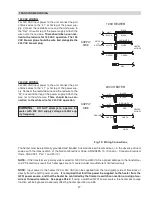
HIGH LIMIT REMOVAL
1. Shut off main electrical power switch to heater.
2. Remove front door.
3. Remove defective high limit and replace with a
new high limit.
4. Replace inspection panel.
NOTE:
An erratic high limit is often characteristic of an
internal heat exchanger problem, e.g. scale build-up,
defective bypass. Refer to Troubleshooting section
(starting on page 42).
The heater is equipped with two automatic high limits.
Both are located in the inlet/outlet header. One is set
at 135°F and the lower one is set at 160°F.
40
TIME CLOCK/FIREMAN’S SWITCH
To operate the heater with a time clock, connect the
timer to the fireman’s switch connection in the heater’s
wiring. The time clock should be of the dual switch
type and set to shut off the call for heat to the pool
heater 15 to 20 minutes prior to shutting down the pool
pump. The fireman’s switch connection is located on
the 6-pin header connected to the digital control board.
Splice into the red wire jumper tagged “Where neces-
sary add Fireman’s switch circuit here” to connect the
time clock.
The fireman’s switch connection must
be a dry contact and must not supply power to the
heater. Powering the fireman’s switch connection
externally may damage the heater, and is not cov-
ered by warranty.
Do not exceed 50 ft of total wiring using 18 AWG
stranded copper wire rated for 105ºC (221ºF) mini-
mum.
NOTE:
When using a time clock, the heater will dis-
play “
Clock/ Fireman Sw
” when the fireman’s switch
is open, indicating that the time clock has shut off the
call for heat.
HIGH LIMITS
This standard, dual-purpose control, mounted and
wired in series with the main gas valve, shuts off
heater in case of pump failure or low water flow.
FLOW SWITCH
AIR PRESSURE & BLOCKED VENT SWITCHES
This heater is equipped with an air pressure switch to
prove the operation of the blower before allowing the
ignition control to begin a Call for Heat. It is also
equipped with a blocked vent pressure switch to pre-
vent the operation of the heater when too much of the
vent is blocked.
The two switches appear similar and are mounted next
to each other on the heater. They can be distin-
guished by their mounted positions and by the pres-
sure settings printed on the labels. See Fig. 33.
BLOCKED VENT SWITCH
0.4 ”W.C.
AIR PRESSURE SWITCH
2.5 ”W.C.
ADJUSTING VALVE MANIFOLD PRESSURE
1. Remove the cap to gain access to the adjustment
screw.
2. Turn the adjustment screw clockwise to increase
pressure. (For example, at -0.6”W.C. turning
clockwise will increase the pressure to -0.5”W.C.,
-0.4”W.C., etc.)
3. Install the cap before reading the manifold pres-
sure.
Fig. 32: Flow Switch
Fig. 31: High Limit
Fig. 33: Air Pressure & Blocked Vent Switch
Содержание 259B
Страница 13: ...13 Florida Building Code Fig 6 Florida Building Code 2010 Tie Down Method...
Страница 32: ...32 WIRING DIAGRAM...
Страница 44: ...44 SECTION 6 REPLACEMENT PARTS...
Страница 48: ...www raypak com Raypak Inc 2151 Eastman Avenue Oxnard CA 93030 805 278 5300 Fax 805 278 5468 Litho in U S A 48...


