56
Introduction
7
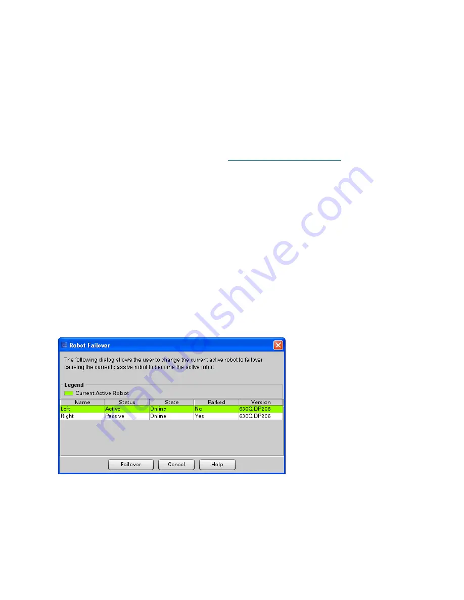
Verify the robots are ready by confirming the following:
•
Name:
Both the left and right robots must be displayed.
•
Status
: One robot must be
Active
; the other robot must be
Passive
.
•
If the status for either robot indicates
Pending
, wait until it changes to active or passive.
Pending indicates it is still performing its self test.
NOTE:
The screen does not update
dynamically, so close the screen, wait a few minutes, and check again.
•
If the status for either robot indicates
Failed
, troubleshoot and fix before continuing.
•
State:
Both robots must be online.
•
Generation:
Both robots must be Gen 2.
8
Click
Close
to close the screen and proceed to
Running IVT and Troubleshooting
on page 56.
Running IVT and Troubleshooting
The IVT uses the active robot for all its tests. The passive robot is inactive during IVT. In order to test both
robots, you must run the full IVT on the active robot, then fail over and run just the Accessor FRU tests on
the newly active robot, as follows:
1
Run IVT on the currently active robot by following all of the instructions in the chapter "Installation
Testing and Verification" in the
Scalar i6000 Installation Guide
. If any problems or tickets occur,
troubleshoot and retest until all tests pass. Then return here.
2
Perform a robot failover so that the currently passive
robot becomes the active robot.
a. On the LMC, make sure you are viewing the physical library (select
View
and click the name of
the physical library).
b. Select
Tools > Library > Robot Failover
.
The Robot Failover dialog box appears. The currently active robot is highlighted.
c. Click
Failover
.
d. Click
Yes
to confirm you want to fail over.
The library fails over and the previously passive robot becomes the active robot. A Success
dialog appears.
e. Click
OK
to close the success dialog.
f.
Click
Cancel
to close the Robot Failover dialog box.
Содержание Scalar i6000
Страница 14: ...14 Introduction Figure 1 Power Rail Position in Module Two bridge clamps connect adjacent rails...
Страница 15: ...Scalar i6000 Installation Guide Super Doc 15 Figure 2 Power Rail Front 4 pin and 3 pin connectors...
Страница 23: ...Scalar i6000 Installation Guide Super Doc 23 Figure 6 Installing Bottom and Middle Racks...
Страница 24: ...24 Introduction Figure 7 Middle X Axis Gear Rack...


