4
Introduction
Aligning and Bolting the Frames
(Same as Gen 1 Task)
1
Using the corner edges of the frames as a rough alignment, position the frames together so the
attachment bolt holes are aligned.
Verify that the attachment holes are aligned. If necessary, adjust the frame legs to better align the
attachment bolt holes.
2
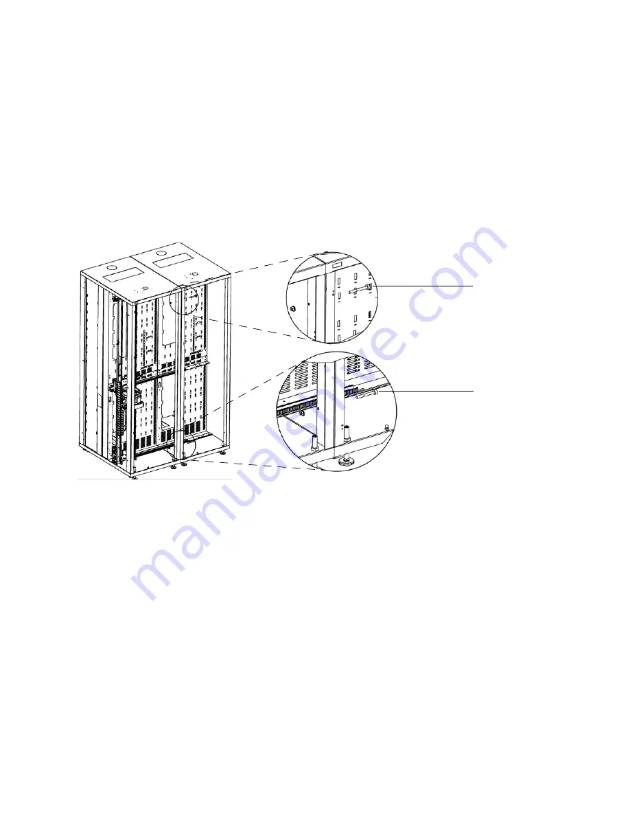
Repeat the following steps for the front lower bolt, front upper bolt, back lower bolt, and back upper bolt,
in that order:
a. Insert the attachment bolt from right to left into the attachment hole
b. If the bolts do not slide smoothly into the holes, raise the appropriate leveling legs until they do.
c. Once the bolts are inserted, loosely thread the nuts onto the bolts.
front upper bolt
front lower bolt
Содержание Scalar i6000
Страница 14: ...14 Introduction Figure 1 Power Rail Position in Module Two bridge clamps connect adjacent rails...
Страница 15: ...Scalar i6000 Installation Guide Super Doc 15 Figure 2 Power Rail Front 4 pin and 3 pin connectors...
Страница 23: ...Scalar i6000 Installation Guide Super Doc 23 Figure 6 Installing Bottom and Middle Racks...
Страница 24: ...24 Introduction Figure 7 Middle X Axis Gear Rack...


