Scalar i6000 Installation Guide Super Doc
55
21
Make sure all the library power supplies are plugged in to a grounded AC power source.
22
Close the doors and power on the library as follows:
a. Make sure all the library power supplies are plugged in to a grounded AC power source.
b. On the power distribution unit(s), set the circuit breaker switch to the up (I) position.
c. Press the
Power
button on the indicator panel.
Verifying Both Robots are Ready for IVT
Before you can test that everything is working properly after the upgrade, you must verify that both robots
are online.
1
Allow 30 minutes for the library to boot. During the bootup, the following occurs:
Robotics start initializing. The active (left) robot performs configuration (scans drive, magazine, and I/E
station fiducials). Then the active robot (left robot) performs a calibration and inventory, and then
performs its robot self test (RST). When complete, the library comes ready (solid green
Ready
LED on
front panel, also indicated on the touch screen). The passive robot also performs calibration and its
robot self test (RST) but it might take longer to finish than the active robot. Wait till both are done before
proceeding. To check that both robots completed RST, do the following.
2
Log on to the LMC.
3
Wait for robotics to become enabled (the
Robotics Enabled
LED on the front panel is on steady). This
can take at least 30 minutes.
4
Check for tickets on the UI and troubleshoot. Resolve and close all tickets before proceeding.
5
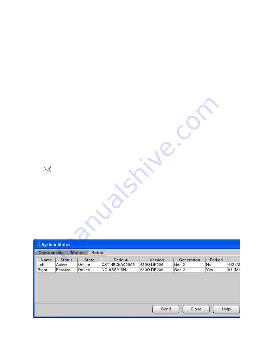
Select
Monitor > System
from the LMC.
The System Status screen appears.
6
Click the
Robot
tab to display the robot system status table.
Note
When the library comes ready and the
Robotics Enabled
and
Power On
indicators turn solid green, this means that the primary robot is ready. It
does NOT mean that the secondary robot is ready (it may still be
performing RST).
Содержание Scalar i6000
Страница 14: ...14 Introduction Figure 1 Power Rail Position in Module Two bridge clamps connect adjacent rails...
Страница 15: ...Scalar i6000 Installation Guide Super Doc 15 Figure 2 Power Rail Front 4 pin and 3 pin connectors...
Страница 23: ...Scalar i6000 Installation Guide Super Doc 23 Figure 6 Installing Bottom and Middle Racks...
Страница 24: ...24 Introduction Figure 7 Middle X Axis Gear Rack...


