background image

7-14 

Field–Replaceable Units (FRUs) 

511010 Rev. 07-01-19

7.10.2


Carriage Assembly Replacement 

This procedure assumes that the Carriage Assembly was removed in Section 7.7.1. 

If the Carriage Assembly is replaced with a different Carriage Assembly, then the li-
brary will require re-calibration. See section 7.17. 

1.

Carefully align the Carriage Assembly with the RLS and slowly slide it in mak-
ing sure that the System connector cable clears the 10U Z Satellite PCBA as the
Carriage Assembly slides to the rear of the RLS.

2.

Carefully finish sliding the Carriage Assembly until the two guide pins connect
with their corresponding holes.

3.

Use a No. 2 Phillips screwdriver to replace the two screws that were removed
earlier.  See Figure 7-10.

4.

Reach into the RLS to the right side of the Carriage Assembly and carefully re-
connect the System connector to the 10U Z Satellite PCBA.

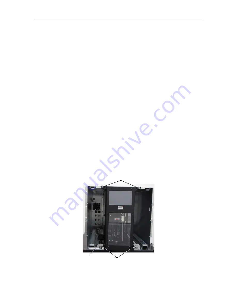
7.11


User Interface Panel Assembly 

P/N 510752-01-7 

RLS-85XX 

P/N 510752-02-5 

RLS-8350 

Tools Required: 

No. 2 Phillips Screwdriver

Figure 7-11   User Interface Panel Assembly shown with Storage Matrices Removed 

Top 2 Screws 

Bottom 2 Screws 

Sheet Metal 

Cable Guard 

Содержание RLS-8350

Страница 1: ...RLS 8350 85XX Series Tape Library Technical Service Manual Document No 511010 Rev 07 01 19 ...

Страница 2: ......

Страница 3: ...pyrighted by Qualstar Corporation It is intended for use by Qualstar s customers and prospective customers to evaluate inte grate operate and maintain Qualstar products Customers and prospective customers may reproduce this document as needed for these uses Reproduction in whole or in part for any other use or by any other party is prohibited without prior written per mission from Qualstar Corpora...

Страница 4: ...s own expense Shielded cables are required for this device to comply with FCC Rules Use shielded cables when connecting this device to others European Union Directive 89 336 EEC and Standard EN55022 Electromagnetic Compatibility Warning This is a Class A product In a domestic environment this product may cause radio interference in which case the user may be required to take adequate measures Euro...

Страница 5: ... Aluminum Robotics Stainless steel Robot guides Steel Exterior panels some frames fasteners Plastic Window cartridge magazines tape cassettes exterior front Copper Internal wiring motors Paper Manuals Items that may have salvage or resale value Tape drives EMI line power filter Reduction of Hazardous Substances RoHS Qualstar is committed to the implementation of RoHS Restriction of the use of cer ...

Страница 6: ...such time as industry data verifies that lead free solders are ca pable of meeting or exceeding the documented reliability and quality standards achieved with lead based solders Until such time as Qualstar replaces lead based solder with lead free solder effected subassemblies must be disposed of appropriately Technical Support Information The best source for service related information is your sy...

Страница 7: ...511010 Rev 07 01 19 v ...

Страница 8: ... Panel 3 2 3 3 1 The Touch Screen 3 3 3 4 Operation Maintenance and Configuration Pages 3 5 3 5 Displaying the RLS Firmware Revisions 3 7 3 6 Alerts Faults 3 8 4 The Maintenance Menu 4 1 4 1 Maintenance Firmware Pages 4 1 4 2 Maintenance Display Log Page 4 3 4 3 Maintenance Display Statistics Pages 4 4 4 4 Maintenance LCD and Touchscreen Checks Page 4 6 4 5 Maintenance Operations Page 4 7 4 5 1 De...

Страница 9: ...wer supply rear of RLS is dark 6 1 6 1 2 When the power is turned on the Handler moves normally the standby power switch illuminates the control panel touch screen is not illuminated 6 1 7 Field Replaceable Units FRUs 7 1 7 1 Introduction 7 1 7 2 Field Upgrades 7 3 7 3 Required Tools and Materials 7 3 7 4 Rack Mounted Libraries 7 3 7 5 Storage Matrices 7 4 7 5 1 Removing a Storage Matrix 7 4 7 5 2...

Страница 10: ...dure 7 18 7 13 2 Tape Drive Assembly Replacement 7 18 7 14 Rack Mounting Kit RLS 8500 7 19 7 14 1 Rack Mounting Kit Removal Procedure 7 19 7 14 2 Rack Mounting Kit Replacement 7 23 7 15 Air Filters 7 29 7 15 1 Replacing an Air Filter in a RLS 85XX library 7 30 7 15 2 Replacing an Air Filter in a RLS 8350 library 7 31 7 16 FastPass Elevator Assembly 7 32 7 16 1 FastPass Elevator Assembly Removal Pr...

Страница 11: ...nformation about the SCSI interface or other information outside the scope of this manual please refer to the appropriate documents listed below Subject Document Qualstar Documen t Number Specifications RLS 8500 Tape Library Product Specification 511001 Specifications RLS 8350 Tape Library Product Specification 511002 Installation and Operation RLS 8350 85XX Series Tape Li brary Installation and O...

Страница 12: ...essed or implied that the manual is error free Qualstar reserves the right to make changes at any time without prior no tification The Qualstar RLS is a sophisticated state of the art computer peripheral It may on ly be serviced by an authorized service technician who is experienced with the opera tion and maintenance of tape libraries and only after reading and understanding this manual and the R...

Страница 13: ...com ply with the handling operating or service instructions found in a CAUTION paragraph In addition useful information and tips may be found throughout the document in the following formats NOTE SPECIAL ATTENTION to explanatory statements found in a NOTE paragraph will help you avoid mistakes and or save time NOTICE A NOTICE box contains additional important information not covered by the other t...

Страница 14: ......

Страница 15: ... O Ports 1 1 1 1 Optional I O Ports 0 1 0 1 Cartridges per I O Port 4 4 4 4 Barcode Reader Standard Standard Standard Standard Hot swap Tape Drive Carriers Standard Standard Standard Standard N 1 Hot Swappable Power Supply Modules Optional Optional Optional Optional FastPass Elevator Expansion option Optional Optional Optional Optional Includes right side Storage Matrix without I O port Includes r...

Страница 16: ...mber of Drives Number of Cartridges in Magazines Figure 2 1 Model Number Identification Scheme This manual applies to all models The installation and operation of the various mod els is virtually identical Differences among the models are noted where required Figure 2 2 RLS 8350 External Dimensions ...

Страница 17: ...applications They were de signed for use in an office environment MODEL WEIGHT FULLY LOADED LBS KG EMPTY WEIGHT LBS KG RLS 8350 166 LBS 75 3 KG 87 LBS 39 5 KG RLS 8560 193 LBS 87 5 KG 123 LBS 55 8 KG RLS 85120 with 1 I O port 227 LBS 103 0 KG 136 LBS 61 7 KG RLS 85120 with 2 I O ports 228 LBS 103 4 KG 139 LBS 63 1 KG Includes rack mount kit and a full complement of tape drives and tape cartridges ...

Страница 18: ...belts Feedback is provided by hall effect sensors with optical end of travel sensing Car tridge gripping is accomplished using a solenoid for simplicity and de pendability The linear axes are riding on linear ball bearings and the ro tating axis is supported on ball bearings This results in high reliability long life and nearly zero maintenance for the robotics 2 2 2 Sensors Optoelectronic Interru...

Страница 19: ...on and speed of the axis of the robot that it oper ates Modulated Optoelectronic Sensors These are used where the distance between the emitter and detector is greater than allowed by simple optoelectronic sensor pairs These sensors consist of an LED emit ter which is modulated and a detector which senses the modulated light One of these sensor pairs is used to detect the presence of cartridges in ...

Страница 20: ... Labels Barcode labels must conform to ANSI AIM BCI 1995 Uniform Symbology Specifica tion Code 39 Please refer to PIN 040 at www qualstar com for more information By default the RLS expects no check characters in each label All of the labels within the RLS must match the configuration setting for the check character 2 3 Component Identification Most of the major components are common to all models...

Страница 21: ...els Figure 2 4 and Figure 2 5 show the location of the major components in the library Figure 2 4 RLS as seen from the rear Figure 2 5 RLS as seen from the front Expansion Card Slots Control Electronics Power Supply Modules Power Inlet Line Fuse and Rocker Switch Tape Drives ...

Страница 22: ...dability The linear axes are riding on linear bearings and the rotating axis is supported on ball bearings The entire robotic handler is a removable as a single unit through the front panel without removing the library from the equipment rack Figure 2 6 RLS Handler RLS 85XX shown 2 3 3 Field Replaceable Units FRUs Many of the library s major components are available separately as Field Replaceable...

Страница 23: ...left storage matrix Figure 3 1 shows the various features of the front panel The library may be configured to con tinue operation while either of the I O port s is extended Figure 3 1 RLS 85XX Front Panel 3 1 The Standby Power Switch The standby power switch allows control of the library s power from the front panel 3 2 The Key Locks The storage matrices are secured with a key operated lock The li...

Страница 24: ...l Panel The control panel is a color LCD with a touch screen overlay and an audible alarm The operator may use the control panel menus to configure and operate the RLS and monitor its status It can also be used to add or remove cartridges Left Side Storage Matrix Right Side Storage Matrix ...

Страница 25: ...lus may be used if desired Figure 3 3 The Home Page The five main pages Home Operation Maintenance Configuration and Private are accessed by pressing either the left or right arrows in the page title box at the top right of each page Note that the Private page is password protected for the protected service pages and will not appear unless the appropriate password has been entered It is intended o...

Страница 26: ...ght side of the screen underneath the page title box As seen in Figure 3 5 the Operation page contains Drive Element Status Move Cartridge Position Handler and Quick Operation sub pages Figure 3 5 Operation Page Sub pages When there are additional tables or pages to be displayed in the main field of a page a set of up and down arrow buttons will be shown Pressing either of these arrows will allow ...

Страница 27: ... for the user and lets the user perform off line tasks associated with the operation of the RLS The Operation menu is described in detail in the RLS 8500 Series Tape Library Installation and Operation Manual Qualstar document number 511000 When libraries are interconnected by the FastPass elevator expansion option some of the menus will change slightly to represent the individual libraries and or ...

Страница 28: ...he sec ond library cabinet and by double tapping on either the 1 or 2 when highlighted on the left side of the touch screen a global view will appear which shows the inventory of both libraries on the same screen Figure 3 8 Additional menu examples from Libraries with the FastPass Elevator Expansion Option Library Cabinet 1 view Library Cabinet 2 view Global View combining Library Cabinet 1 Librar...

Страница 29: ...intenance page Figure 3 9 The Firmware Pages Touch either arrow in the page title box at the top right until the Maintenance page appears When at the Maintenance page touch the Firmware button if the Firmware page is not already open This will display the Maintenance Firmware Satellite Revi sions page Pressing the downward arrow will bring up the Mainte nance Firmware Repository page ...

Страница 30: ...will display in the information box at the bottom of the Home page and remain visible until dismissed by the operator Figure 3 10 Alert Fault Example Alert and Fault messages can be dismissed by pressing the Dismiss Fault button on the Home page or on the Operation page under Quick Operation ...

Страница 31: ...sed to display detailed information about the RLS and its operating history and to test the functionality of the LCD Touchscreen 4 1 Maintenance Firmware Pages The Maintenance Firmware pages allows for satellite firmware revision to be identi fied and old versions of the Executive and Control Panel firmware sets to be deleted ...

Страница 32: ...ing the Edit button then touching the blue chevron under the Action column next to the desired Firmware Id A red negative sign will then appear next to it under the Action column signifying that it has been tagged for deletion Note that touching the Delete button will eliminate all firmware that has been tagged for deletion while pressing the Cancel button will remove all the tags and no firmware ...

Страница 33: ...r Technical Support technician then the technician directs the User to look only at problem specific logged data Finally the logged data is evaluated to help de termine the cause of the problem If intermittent or unusual system problems are encountered we recommend that the user contact Qualstar s Technical Support Department first before the user tries to analyze the problem using the logged acti...

Страница 34: ... summary of events that have oc curred between the time the RLS was built and the current time All values are deci mal counts of the number of times an event has occurred Displayed values include Carriage Changer SCSI and any drive carrier operations Figure 4 5 Display Statistics Carriage Page Figure 4 6 Display Statistics Changer Page ...

Страница 35: ...511010 Rev 07 01 19 The Maintenance Menu 4 5 Figure 4 7 Display Statistics Changer cont and SCSI Page Figure 4 8 Display Statistics Drive Carriers 1 and 2 Page ...

Страница 36: ...and move around the screen to determine touchscreen will track dragging movements Pressing the clear button will revert back to the circle so the check may be repeated and pressing cancel will return to the main LCD and Touchscreen Checks page Figure 4 10 LCD and Touchscreen Checks Track Page Pressing the LCD Color Check buttons White Black Red Green or Blue will turn the entire touchscreen to tha...

Страница 37: ...rate the RLS while Random Moves is generally used when testing or burning in the RLS Figure 4 11 Operations Page 4 5 1 Demonstrations There is the option of allowing the I O Ports to be operated while running demonstra tions which can be turned on or off by touching the Enable IOPorts button When the Run Demo button is touched the library begins a slide presentation on the touch screen and starts ...

Страница 38: ...ption to enable I O Port operation was selected the Open IO buttons will be active otherwise they will be gray and inac tive NOTE To exit demonstration mode a magazine storage matrix must be unlocked 4 5 2 Random Moves Touching the Start button under Random Moves commands the changer to start a continuous sequence of random cartridge moves These moves will continue until the same button now named ...

Страница 39: ...e the changer It is also a privileged password protected page This means that a password must be set to gain access to the items in the Private page The password to the Pri vate page is cleared before the RLS is shipped from the factory because the page is intended only for use by field service personnel Passwords are used to protect the RLS configuration against unauthorized or unin tentional cha...

Страница 40: ...el dependent 5 1 1 Setting a Password The libraries Security Identity passwords are entered on the Configura tion Library Identification and Security screen To enter a password press the Edit button which will bring up a screen that allows data to be entered as shown in Figure 5 3 Figure 5 2 Configuration Library Identification and Security Screen ...

Страница 41: ...that only the first letter is capital ized Note that changes to the screen will not be saved until the Save button is pressed Pressing the Cancel button will remove all of the current editing and revert to the last saved version of the screen The new password will not take effect until the Save but ton is pressed on the Configuration Library Identification and Security screen as shown in Figure 5 ...

Страница 42: ... None and the Security ID will disappear from the Home Screen Figure 5 5 Security ID on the Home Screen The alternate procedure is to return to the Configuration Library Identification and Security screen then press the Edit button as was done when originally entering the Update password When the screen appears for entering passwords do not enter any characters Simply press the done button and the...

Страница 43: ...he li brary page The Calibrate button should not be pressed without a specific reason for doing so be cause it involves risk For example if the Calibrate command is used incorrectly im proper Handler operation may result Therefore if the Handler is properly picking and placing cartridges and the user does not have a specific reason for using the Cal ibrate command recalibrating the RLS is not reco...

Страница 44: ...ration Calibrated Has the library been successfully calibrated Yes or No Cartridge Present Calibration Present PWM Emitter intensity determined during calibration for the opto pair 1 to 50 Clear Sensor PWM Pulse Width Modulation Drive Emitter intensity determined during calibration for the opto pair 1 to 50 Left Back Emitter intensity determined during calibration for the opto pair 1 to 50 Left Fr...

Страница 45: ...ly completed Yes or No Elevator Lower A Yes means this element of the calibra tion process was successfully completed Yes or No Elevator Upper A Yes means this element of the calibra tion process was successfully completed Yes or No Ioport Left A Yes means this element of the calibra tion process was successfully completed Yes or No Ioport Right A Yes means this element of the calibra tion process...

Страница 46: ...alibrated mechanical position corrections Y IO Port Corrections Left IO Port Calibrated mechanical position corrections Right IO Port Calibrated mechanical position corrections Y Drive Correction Drive Calibrated mechanical position corrections Y Elevator Correction Elevator Lower Calibrated mechanical position corrections Elevator Upper Calibrated mechanical position corrections Y Left Correction...

Страница 47: ...Drive 1 Calibrated mechanical position corrections Drive 2 Calibrated mechanical position corrections Drive 3 Calibrated mechanical position corrections Drive 4 Calibrated mechanical position corrections Drive 5 Calibrated mechanical position corrections Drive 6 Calibrated mechanical position corrections Drive 7 Calibrated mechanical position corrections Z Left Corrections Column A Calibrated mech...

Страница 48: ...n page enables the Frame Grabber utility when the appro priate password has been entered The Frame Grabber is used to capture screen shots which can be viewed by customer service personal or technicians when in the process of diagnosing and servicing the RLS Figure 5 10 The Configurations Page ...

Страница 49: ...hether or not CAN termination is turned on True or False Card Present Set Which backplane slots have cards installed Fan Fault Whether or not if the fan on the backplane cir cuit board has faulted True or False Cabinet Serial No The serial number of the library also displayed on a label on the rear of the library Command TBD TBD Backplane Drives Drive Covered Set Displays a decimal number to repre...

Страница 50: ...alue displays the 5V supply voltage on the Backplane PCBA in millivolts Voltage Share mV Power sharing signal with more than one power supply installed In Millivolts Backplane Power Supplies Good Set Power supplies are functioning properly On Set Power supplies are turned on Present Set Power supplies are present but not on Supply 1 Type Type of power supply installed in this slot Various Supply 2...

Страница 51: ...the way to the back True or False Servo Mode Operating mode of the servo motor Servo Position Servo motor rotor position Servo Status Status of the servo Solenoid PWM Per cent Correct percentage on time for servo winding Carriage Supply Voltages Supply 15 mV This value displays the 15V supply voltage to the Carriage PCBA In Millivolts Supply 24 mV This value displays the 24V supply voltage to the ...

Страница 52: ... the way to the upper posi tion True or False Position Is the elevator currently in the Up or Down posi tion Up or Down Servo Mode Operating mode of the servo motor Servo Position Servo motor rotor position Servo Status Status of the servo Elevator Supply Voltages Supply 15 mV This value displays the 15V supply voltage to the Elevator PCBA In Millivolts Supply 24 mV This value displays the 24V sup...

Страница 53: ...are normal ly set to all be on but can be set individually left center or right to aid in diagnosis proce dures Left Center Right or On Power Switch Pressed Indicates whether the power switch has been pressed to be on or off On or Off Magazine Left Type Describes what is currently in the left side magazine location Ioport is a magazine with an I O Port Slots is a magazine without an I O Port Absen...

Страница 54: ...ans a blank is installed Ioport Slots Absent Ioport Sensor True indicates the right side magazine has an I O port false indicates it does not True or False Latched Sensor True indicates the right side magazine is fully inserted into the library false indicates it is not If the optional I O Port is present true indicates that it is fully latched false indicates it is not True or False Locked Sensor...

Страница 55: ...on the handler is not blocked True or False Left Side True indicates that the Left Side sensor on the handler is not blocked True or False Right Back True indicates that the Right Back sensor on the handler is not blocked True or False Right Front True indicates that the Right Front sensor on the handler is not blocked True or False Right Side True indicates that the Right Side sensor on the handl...

Страница 56: ...e way to the clock wise stop True or False Servo Mode Operating mode of the servo motor Servo Position Servo motor rotor position Servo Status Status of the servo Theta Supply Voltages Supply 15 mV This value displays the 15V supply voltage to the Theta PCBA In Millivolts Supply 24 mV This value displays the 24V supply voltage to the Theta PCBA In Millivolts Table 5 10 Display Satellite Theta Scre...

Страница 57: ...lite Y Screen Section Field Description Option Y Satellite Home Sensor If Y axis access is all the way to the bottom True or False Servo Mode Operating mode of the servo motor Servo Position Servo motor rotor position Servo Status Status of the servo Table 5 11 Display Satellite Y Screen Information ...

Страница 58: ...the way to the back True or False Servo Mode Operating mode of the servo motor Servo Position Servo motor rotor position Servo Status Status of the servo Z Supply Voltages Supply 15 mV This value displays the 15V supply voltage to the Z PCBA In Millivolts Supply 24 mV This value displays the 24V supply voltage to the Z PCBA In Millivolts Table 5 12 Display Satellite Z Screen Information ...

Страница 59: ...anger It uti lizes unused bandwidth on the first tape drive for the robotics interface or the first drive in each partition if the library is partitioned 5 5 1 Display Drive Screen Figure 5 19 The Display Drive Screen Section Field Description Option Drive 1 to 7 maximum Information Valid Indicates whether or not the library considers the information in this field to be valid or not Yes or No Mode...

Страница 60: ...in Gigabytes per second Some tape drives have two ports and if the second port is connected its speed will be shown here Variable Secondary WWPN Some tape drives have two ports and if the second port is connected its assigned WWPN will be shown here Variable Drive 1 to 7 Supplies Enabled Whether or not the tape drive is enabled Fault Is the tape drive functioning properly Yes or No Valid Indicates...

Страница 61: ... that a tape drive is empty or unloaded and acces sible to the changer A No value indicates that a tape drive is loaded and not accessible to the changer Accessible Valid Yes or No A Yes value means the Accessible status for the selected tape drive is valid Occupied Yes or No A Yes value indicates that a cartridge occupies the selected location Occupied Valid Yes or No A Yes value means the Occupi...

Страница 62: ......

Страница 63: ...en the power is turned on no motion occurs the standby power switch does not illuminate the power indicating LED on the power supply rear of RLS is dark 1 Check that the power source is live 2 Check the line fuse in the AC power receptacle turn off the RLS and remove power cord first 6 1 2 When the power is turned on the Handler moves normally the standby power switch illuminates the control panel...

Страница 64: ......

Страница 65: ...en certain FRU s Field Replaceable Units are installed the library will need to be calibrated to adjust for mechanical manufacturing tolerances The RLS has been de signed to detect when it needs to be calibrated and will place a message on the control panel at that time Normal library operation will not continue until the calibration process has been completed CAUTION Static electricity can perman...

Страница 66: ...5XX 510753 09 8 7 5 5 On Storage Matrix Assembly Blank RLS 85XX 510753 10 6 7 6 5 Off Rack Mounting Kit 510756 01 8 7 14 30 Off Drive Filler Assembly 510757 01 6 7 12 5 On Tape Drive LTO 5 SAS 510903 01 6 7 13 5 On Tape Drive LTO 5 FC 510903 02 0 7 13 5 On Tape Drive LTO 5 FC Dual Port 510903 04 0 7 13 5 On Tape Drive LTO 6 SAS 510903 05 7 7 13 5 On Tape Drive LTO 6 FC 510903 06 5 7 13 5 On Tape D...

Страница 67: ...t 7 3 Required Tools and Materials Table 7 3 is a complete list of the tools that would be required to replace every RLS FRU See individual FRU sections of this chapter for the tool needed to replace just that FRU Required Tools No 2 Phillips Screwdriver Door key 3 32 inch Allen Hex Wrench 11 32 inch Open End Wrench or Nut Driver Small Mirror optional Flashlight optional Table 7 3 Required Tools 7...

Страница 68: ...Port RLS 85XX P N 510753 09 8 Storage Matrix Assembly Left Side without I O Port RLS 85XX P N 510753 04 9 Storage Matrix Assembly Left Side RLS 8350 P N 510753 06 4 Storage Matrix Assembly Right Side RLS 8350 Tools Required Door key 7 5 1 Removing a Storage Matrix 1 Power may remain on when performing this procedure 2 Unlock the left or right storage matrix with the key 3 Grasp the matrix at the i...

Страница 69: ...or inserting it in to the library Tilting the storage matrix when it is outside the library may cause tapes to fall from the storage slots and become damaged 6 While securely grasping the top handle of the storage matrix and using your other hand to guide it slide the matrix out of the library 7 Place the storage matrix on a stable surface 7 5 2 Replacing a Storage Matrix 1 Power may remain on whe...

Страница 70: ...Screwdriver Flashlight optional Small Mirror optional 7 6 1 Removing a Storage Matrix Assembly Blank 1 Remove power from the RLS by first pressing the power switch off and then re moving the power cord two power cords if dual redundant power supply mod ules are installed 2 Remove the left side storage matrix as described in Section 7 5 1 3 The Storage Matrix Assembly Blank is secured to the RLS wi...

Страница 71: ...p to step 10 otherwise follow the next step to remove the face of the user interface panel assembly 6 Once both screws from the Storage Matrix Assembly Blank are loosened careful ly pull it off the RLS and set it aside 7 6 2 Replacing a Storage Matrix Assembly Blank This procedure assumes that the Carriage Assembly was removed in Section 7 6 1 1 Align the guide pin on the right side of the Storage...

Страница 72: ...stalled 2 Remove any cables from the Executive PCBA 3 Turn the thumbscrew fasteners counter clockwise until they are fully disengaged 4 Slide the Executive PCBA out of the RLS 7 7 2 Executive PCBA Replacement This procedure assumes that the Executive PCBA was removed in Section 7 7 1 1 Align the Executive PCBA with its opening and push it into the rear of the li brary until you feel it snap into p...

Страница 73: ...ps Screwdriver optional Figure 7 6 Power Supply shown on rear of RLS P N 510550 01 5 shown CAUTION If there is a single power supply installed in the RLS the library needs to be powered off before replacing it Only libraries with two or more power sup plies installed for N 1 capability can have a power supply replaced while the RLS is powered on Power Supply LED Thumb Screw ...

Страница 74: ...gage the thumbscrew fastener and turn it clockwise until it s fully tightened 7 8 3 Hot Removal of a redundant N 1 Power Supply 1 Power may remain on when performing this procedure 2 IDENTITY THE FAILED power supply An alert on the touch screen should in dicate which supply has failed The failed supply s LED will not be illuminated 3 Turn the thumbscrew fastener counter clockwise until it s fully ...

Страница 75: ...ver Power Plate shown on rear of RLS 7 9 1 Cover Power Plate Removal Procedure 1 Use a No 2 Phillips screwdriver to remove the screw that secures the Cover Power Plate to the rear of the RLS 7 9 2 Cover Power Plate Replacement This procedure assumes that the Carriage Assembly was removed in Section 7 9 1 1 Place the Cover Power Plate into the power supply opening with the tabs as shown in Figure 7...

Страница 76: ...pe cartridges Tools Required No 2 Phillips Screwdriver Figure 7 8 Carriage Assembly shown with the User Interface Panel Assembly removed 7 10 1 Carriage Assembly Removal Procedure 1 Remove power from the RLS by first pressing the power switch on the rear of the library off and then removing the power cord two power cords if dual redundant power supply modules are installed 2 Follow the steps in Se...

Страница 77: ...with the System Connector 4 There are only two screws on the front of the Carriage Assembly that secure it to the RLS Use a No 2 Phillips screwdriver to remove the both screws They are the lower and larger pair as shown in Figure 7 10 Figure 7 10 The Carriage Assembly Screws 5 With the screws removed simply slide the Carriage Assembly out of the RLS Remove these 2 Screws Disconnect the System Conn...

Страница 78: ... the Carriage Assembly slides to the rear of the RLS 2 Carefully finish sliding the Carriage Assembly until the two guide pins connect with their corresponding holes 3 Use a No 2 Phillips screwdriver to replace the two screws that were removed earlier See Figure 7 10 4 Reach into the RLS to the right side of the Carriage Assembly and carefully re connect the System connector to the 10U Z Satellite...

Страница 79: ...e RLS that secure the User Interface Panel As sembly Use a No 2 Phillips screwdriver to remove the two screws along the bot tom as shown in Figure 7 11 Note that the screw securing the sheet metal cable guard on the bottom left side is longer than the other three screws 5 While pressing down on the release tab of the connector carefully disconnect the User Interface Panel Assemblies cable from the...

Страница 80: ...Carefully reconnect the User Interface Panel Assemblies cable 4 Place the sheet metal cable guard on the RLS making sure the tab is in the slot Secure the guard using a No 2 Phillips screwdriver and the long screw that was removed earlier 5 If a storage matrix assembly blank was installed on the right side replace as shown in Section 7 6 2 7 12 Drive Filler Assembly P N 510757 01 6 A Drive Filler ...

Страница 81: ...rary until you feel it stop 2 Use a No 2 Phillips screwdriver to replace and tighten the two screws that se cures the Drive Filler Assembly to the rear of the RLS 7 13 Tape Drive Assemblies P N 510903 01 6 Tape Drive LTO 5 SAS P N 510903 02 0 Tape Drive LTO 5 FC P N 510903 04 0 Tape Drive LTO 5 FC Dual Port P N 510903 05 7 Tape Drive LTO 6 SAS P N 510903 06 5 Tape Drive LTO 6 FC P N 510903 08 1 Ta...

Страница 82: ...il they are fully disengaged 4 Slide the Tape Drive Assembly out of the RLS 7 13 2 Tape Drive Assembly Replacement This procedure assumes that the Tape Drive Assembly was removed in Section 7 13 1 1 Power may remain on when performing this procedure 2 Align the Tape Drive Assembly with its opening and push it into the rear of the library until it is seated 3 Engage the two thumbscrew fasteners and...

Страница 83: ...eady been removed skip to Step 9 to begin the rack removal procedure DANGER THE RLS WEIGHS UP TO 222 LBS 100 7 KG AND TWO PEOPLE ARE NEEDED TO LIFT IT HANDLING THE RLS ALONE COULD RESULT IN BACK INJURY OR OTHER ACCIDENTS 1 Remove power from the RLS by first pressing the power switch off and then re moving the power cord two power cords if dual redundant power supply mod ules are installed 2 Discon...

Страница 84: ...one on each side that secure the library to the front rack posts See Figure 7 15 Figure 7 15 Removing the screws that secure the Library to the Rack 5 Slide the library out on the rack rails until about 8 inches is sticking out the front of the rack posts Flange Remove both screws to release the library from the rack ...

Страница 85: ...Qualstar Technical Support for a replace ment set if the front hand holds that originally shipped with the RLS cannot be located Use a Number 2 Phillips screwdriver to install the two screws that se cure the hand holds to the left and right sides of the RLS Figure 7 16 Installing the Front Hand Holds on the Library Front Hand Hold Install these 2 Screws to secure a Hand Hold ...

Страница 86: ...lled have two or more people slide the library out of the rack and lift the library by grabbing the front and rear hand holds as seen in Figure 7 17 Figure 7 17 Library ready to be removed from the Rack 8 Carefully place the library down on a sturdy surface Front Hand Holds Rear Hand Hold ...

Страница 87: ...s from the two front rack posts 7 14 2 Rack Mounting Kit Replacement This procedure assumes that the Rack Mounting Kit was removed in Section 7 14 1 1 If the rack is not going to be placed into the same location decide where the rack rails are to be mounted We recommend marking the position where each rack rail assembly bracket is to be mounted 2 The rack rail assembly must be sized to fit the dis...

Страница 88: ...ed to be moved so that the mounting holes of the brackets will be in contact with the inside edge of the rack posts Note that the long bracket must be mounted at the rear of the rack Refer to Figure 7 19 Figure 7 19 Rack Rail Assembly between the Front and Rear Rack Posts 2 38 6 38 9 38 13 38 Rear Rack Post Front Rack Post Short Mounting Brackets Washer and Rack Rail Mounting Screw Long Mounting B...

Страница 89: ...simply adjust the brackets of the new assemblies to match the old ones 6 If sizing the rack rail assembly between the rack posts and one rack rail assem bly has had its brackets moved so that they are in contact with the inside edge of the rack posts reposition the brackets on the other rack rail assembly to match 7 Position a rack rail assembly between the front and rear posts so that the brack e...

Страница 90: ...mpt to replace the washers with any other washer that has not been provided by Qualstar Figure 7 21 Screws and Washers securing a Rack Rail Assembly to the Rack Posts 9 Using a 11 32 wrench tighten all of the nuts that were loosened in step 3 when the brackets were moved on the rack rail assembly 10 Repeat Steps 7 through 10 to attach the remaining rack rail assembly to the rack 11 The library wil...

Страница 91: ... same procedure for the right front rack post making sure that the cage nut is at the same height as the left side 14 The library is now ready to be placed back on the rack rail assemblies 15 Have two or more people lift the library by grabbing the front and rear hand holds as seen in Figure 7 23 Place it between the rack posts and slide it back on the rack rails until about 8 inches remains stick...

Страница 92: ...re 7 24 Removing the Front Hand Holds from the Library 17 Store the front hand holds and their mounting screws in a safe location so they may be re used if the library is removed from the rack 18 With the hand holds removed slide the library all the way back into the rack until the flanges on the sides touch the front rack posts Figure 7 25 The Library fully inserted into the Rack Flange Install o...

Страница 93: ...ilter attached to the front of each storage matrix This filter keeps dust and dirt from entering the enclosure as its presence could degrade the re liability of the tape drives and media If the filter becomes clogged with dust and dirt the amount of airflow will be diminished Diminished airflow could cause the tape drives to run hotter again degrading their reliability Therefore it is important to...

Страница 94: ...dirty enough to be replaced and is being reinstalled make sure that the side that was facing the inside of the library is placed in the same direc tion as it was when it was removed Reversing the direction of an old air filter may cause dirt to be transferred into the library 4 Slide the air filter past the air filter tab until it is touching the stops on the stor age matrix front panel and then t...

Страница 95: ...irty enough to be replaced and is being reinstalled make sure that the side that was facing the inside of the library is placed in the same direc tion as it was when it was removed Reversing the direction of an old air filter may cause dirt to be transferred into the library 4 Insert the air filter into the opening in the front of the storage matrix making sure that it is centered 5 Flatten the ai...

Страница 96: ... parts 1 If the libraries are powered up press the Park Rear button on the Park Handler section of the libraries Home Page to move the handler to the rear of the library 2 Remove power from both libraries by first pressing the power switch off and then removing the power cord two power cords if dual redundant power supply mod ules are installed Upper elevator ex pansion module Lower elevator ex pa...

Страница 97: ... on Upper Module 4 Use a Number 2 Phillips screwdriver to remove the eight screws that secure both the upper and lower elevator expansion units See Figure 7 30 Figure 7 30 The Upper and Lower Elevator Expansion Modules into the Library Remove these 8 Phillips head screws Upper elevator expansion module Lower elevator expansion module Elevator module cable LED on upper elevator expansion module ...

Страница 98: ...r if the elevator is in its lower position when it is being removed 6 Look through the opening where the lower elevator expansion unit was removed and confirm that the elevator mechanism is in its upper position as shown in Figure 7 31 If it is not in this position reach into the library and push it up wards until it is completely in the upper position Figure 7 31 The Elevator Mechanism in its Upp...

Страница 99: ... into the upper library as shown in Figure 7 33 Make sure that the elevator mechanism is in its upward position so that it does not interfere with anything inside the library as it is slid in See Figure 7 32 Figure 7 32 Upper Elevator Mechanism Elevator Mechanism in It s upward position Upper Elevator Expansion Module Elevator Mechanism shown in It s upward position Do not attempt to install or re...

Страница 100: ...per Library 2 Carefully slide the lower elevator expansion module into the lower library as shown in Figure 7 34 Figure 7 34 Sliding the Lower Elevator Expansion Module into the Upper Library Secure with 8 Phillips head screws Upper elevator expansion module Lower elevator expansion module Lower elevator expansion module ...

Страница 101: ...ther cable that has not been provided by Qualstar 5 There is a small LED light on the upper elevator expansion module where green indicates that power and data connectivity are good between the upper and low er modules A red LED is an indication that one end of the cable is not attached correctly or one of the libraries is not powered up 6 Once the black elevator module cable is attached between t...

Страница 102: ...of Home Page Screen 1 To perform the calibration procedure the Private page must be accessed and it is a privileged password protected page This means that a password must be set to gain access to the items in the Private page 2 The libraries Security Identity passwords are entered on the Configura tion Library Identification and Security screen See Figure 7 37 To enter a password press the Edit b...

Страница 103: ...first letter is capitalized 4 Note that changes to the screen will not be saved until the Save button is pressed Pressing the Cancel button will remove all of the current editing and revert to the last saved version of the screen The new password will not take ef fect until the Save button is pressed on the Configuration Library Identification and Security screen as shown in Figure 7 39 Figure 7 3...

Страница 104: ...e rows must be emptied of any tape cartridges Please look at the li braries control panel for instructions detailing exactly which rows must be emptied for individual models 7 After the tape cartridges have been removed press the Calibrate button to begin the calibration process which may take several minutes to complete 8 After the libraries have successfully been calibrated the current password ...

Страница 105: ...will set the Security Identity to its default which is None and the Security ID will disappear from the Home Screen 11 The alternate procedure is to return to the Configuration Library Identification and Security screen then press the Edit button as was done when originally en tering the Update password When the screen appears for entering passwords do not enter any characters Simply press the don...

Страница 106: ......

Страница 107: ...tive processors task to check the revision and integrity of each satellite processor s firmware whenever RLS power is applied If the Executive processor has just been revised as described above it will then immediately revise any satellite processor s firmware that is outdated Changing a FRU may also cause the Executive processor to update the firmware in the new FRU It s conceivable that installi...

Страница 108: ...sitory status screens under the Maintenance menu Touch either arrow in the page title box at the top right until the Maintenance page appears When at the Maintenance page touch the Firmware button if the Firmware page is not already open This will display the Maintenance Firmware Satellite Revisions page Pressing the downward arrow will bring up the Maintenance Firmware Repository page Figure 8 1 ...

Страница 109: ...y either clicking on the Browse button or typing the file path to the firmware file Figure 8 2 Sample of the Library Firmware Upload Screen 2 Click on the Upload Firmware button to begin the uploading process 3 The upload process will only take a few seconds but note that after the upload begins browsing to another page will stop the firmware uploading process 4 A progress screen will appear as th...

Страница 110: ...a screen will appear that shows that the file was written successfully See Figure 8 4 Figure 8 4 Sample of the Library Firmware File was written successfully Screen 6 Firmware files can also be deleted by simply clicking the Delete button next to the file desired to be deleted ...

Страница 111: ...atrix Assembly Blank 2 Install the new Storage Matrix Assembly 9 2 1 Installing a Model Expansion Kit This procedure requires one expansion kit which includes a Right Side Storage Ma trix Assembly either with or without an I O port P N 510753 02 3 Storage Matrix Assembly Right Side with I O Port P N 510753 03 1 Storage Matrix Assembly Right Side without I O Port Tools Required No 2 Phillips Screwd...

Отзывы: