


MVI56E-FLN ♦ ControlLogix Platform
Start Here
FA Control Network Ethernet Communication Module
User Manual
ProSoft Technology, Inc.
Page 15 of 155
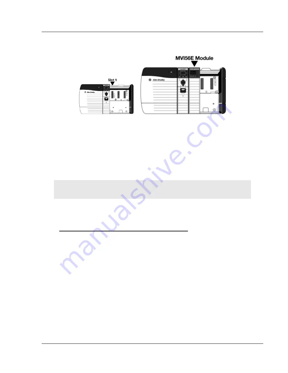
1
Align the module with the top and bottom guides, and then slide it into the
rack until the module is firmly against the backplane connector.
2
With a firm, steady push, snap the module into place.
3
Check that the holding clips on the top and bottom of the module are securely
in the locking holes of the rack.
4
Make a note of the slot location. You must identify the slot in which the
module is installed in order for the sample program to work correctly. Slot
numbers are identified on the green circuit board (backplane) of the
ControlLogix rack.
5
Turn power ON.
Note:
If you insert the module improperly, the system may stop working or may
behave unpredictably.
1.6
Installing ProSoft Configuration Builder
To install ProSoft Configuration Builder from the web site
1
Download the latest version of PCB from www.prosoft-technology.com.
2
Run the install file.
This action starts the installation wizard for
ProSoft
Configuration Builder
.
3
Click
N
EXT
on each page of the installation wizard. Click
F
INISH
on the last
page of the wizard.


