Prism
Operation Manual Issue 2.00
Page 6.8
6.1.4.
Amplitude (menu 1.4.)
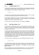
This selection measures the peak-to-peak differential carrier amplitude for either the
co-axial input or the balanced input. The measurement is made regardless of lock state,
and is displayed in volts or millivolts according to voltage.
Amplitude =
562mV [P-P]
The measurement is made using an absolute peak detection method, and so is subject
to inclusion of any ringing or overshoot on the carrier transitions.
When measuring analogue audio signals, note that the low-frequency response only
extends down to 300Hz in this sub-menu. For audio frequencies, use the LoBand
Amplitude sub-menu which extends down to 28Hz.
To return to the `Carrier Tests' level of the menu system, press [EXIT].
6.1.5.
Eye Closure (menu 1.5.)
The Eye Closure measurement is similar in use to the Data Jitter measurement (see
section 6.1.3.) in that it measures intersymbol interference or pulse smearing.
However, this selection does so in a special way which is designed to be independent
of program or status activity.
This is done by measuring the duration of the first short pulse in the X preamble, and
comparing this result with the ideal duration, derived from the measured sampling rate.
The reduction in the duration of this single-cell pulse, following a three-cell symbol, is
a useful static measure of the intersymbol interference which manifests itself as Data
Jitter when program is present. It also usually represents the worst-case eye closure
in the data stream since the 3:1 symbol ratio is the worst possible in the AES3 format.
This is described further in appendix A.
The result is shown in nanoseconds, also as a percentage of the ideal '1UI' value:
Closure @ZeroX =
10.2ns, 6.3%UI
The measurement of eye-width reduction can be made at the zero-crossing point (as
in the example shown above) or at a 'slicing level' equivalent to the 200mV P-P point
referred to in the interface specification. The selection is made using the
[EDIT/CLEAR] key.
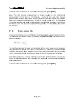
When measuring Eye Closure whilst the Signal Generator is on, it is necessary that the
test input be phase-locked to the Generator (or vice versa) - see section 6.1.2.1.


