Prism
Operation Manual Issue 2.00
Page 7.9
7.3.3.3.
Set switches
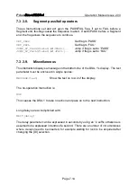
These Instructions have no parameters and are used to set the DSA-1 switched
operating parameters:
SELECT_COAX
Digital Input (DI) selection
SELECT_XLR
SELECT_OPT
SELECT_CHANA
Sub-frame (channel) selection
SELECT_CHANB
SELECT_JITTERCF_HI
Jitter PLL corner-frequency selection
SELECT_JITTERCF_LO
SELECT_EYE_AT_ZEROX
Threshold voltage for eye-narrowing measurement
SELECT_EYE_AT_200MV
SELECT_LOZ
Select DI termination state
SELECT_HIZ
CLEAR_ERROR_COUNT
Clear the biphase/parity error counter
CLEAR_LOG
Clear the Results Log
INSERT_LOG_BLOCK
Insert a Block Marker into the Results Log
CLEAR_LOG_LAST_BLOCK
Clear the Results Log back to last Block Marker
7.3.3.4.
Test binary results
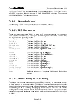
These Instructions cause a snapshot of a particlar DSA-1 operating parameter to be
loaded into the 16-bit Test Register. For most of these Instructions, the value is only
a single bit, which is loaded into the least-significant bit of the Test Register with the
upper 15 bits zeroed. Where indicated, a longer value is loaded at the least-significant
end of the Test Register with the remaining upper bits zeroed.
TEST_UNLOCK_BIT
CARRIER panel 'FAIL' LED; 1 if lit
TEST_NFAIL_BIT
CARRIER panel 'N.FAIL' LED; 1 if lit
TEST_BLOCKERR_BIT
CARRIER panel 'BLOCK' LED; 1 if lit
TEST_ALOG_BIT
CARRIER panel 'ALOG' LED; 1 if lit
TEST_AUX_BITS
DATA panel 'AUX' LED; 1 if lit
TEST_AUDL_BITS
DATA panel 'AUDIO' (low-bits) LED; 1 if lit
TEST_AUDMAIN_BITS
DATA panel 'AUDIO' (main bits) LED; 1 if lit
TEST_V_BIT
DATA panel 'V' LED; 1 if lit
TEST_U_BIT
DATA panel 'U' LED; 1 if lit
TEST_ANEB_BIT
DATA panel 'A
g
B' LED; 1 if lit
TEST_CRCERR_BIT
DATA panel 'CRC ERROR' LED; 1 if lit

