


XTR-PX2-C0006-IN004 leveling w/o Stand
1
Leveling procedure when we don't use STAND
Apr. 28th 2017
Preparation:
- thin metal plate: 30 mm x 30 mm , thickness=0.4 mm, four pieces (maximum) = Spacer plate
Procedure
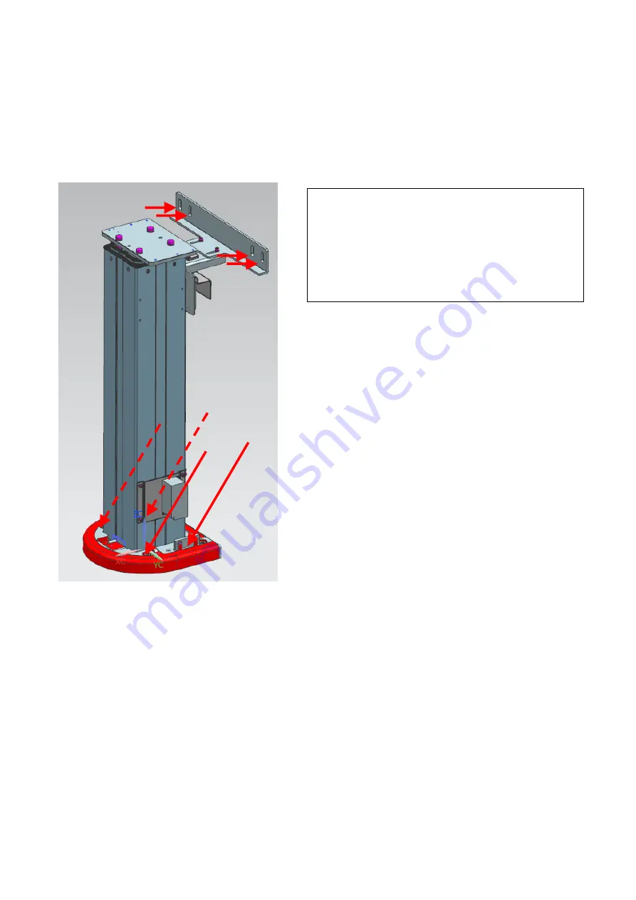
Step1
Tentatively fasten the floor screws ( 4 pieces ).
Then, tentatively fasten the wall fixture 4 screws.


