7-12 SAFETY FEATURES AND EQUIPMENT
PA1628 H3-41, H3-45 Operator’s Manual
3.
Remove the wheel nuts and remove the
wheel;
4.
Mount the spare wheel over the studs, being
careful not to damage the stud threads;
5.
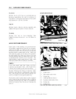
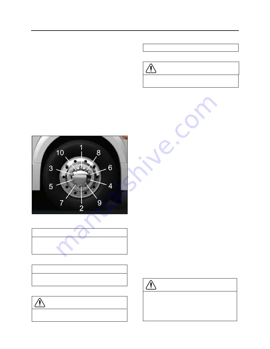
Screw in the wheel nuts according to the
sequence shown in the following figure and
tighten slightly more and repeat the
sequence a few times to position the wheel
correctly. Once tightening induces wheel
spin, lower the coach for final tightening;
6.
Tighten the nuts progressively in the
sequence shown. Final tightening should be
done using a torque wrench. Dry tightening
torque is 450 – 500 lbf-ft (610 – 680 Nm)
for steel as well as for aluminum wheels.
TIGHTENING SEQUENCE
13018
NOTE
Periodically check the spare tire inflation
pressure. Tire pressure should be the
maximum pressure specified in the chart.
NOTE
Periodically check that the spare is securely
fastened in its compartment.
CAUTION
Before driving, be sure the flat tire, track, jack
and tools are securely reinstalled in their
respective compartments.
CAUTION
Check that the bumper is securely closed
shut before driving.
SUPER SINGLE TIRE REPLACEMENT
Increase tire pressure to 125 lbs/in
2
(862 kPa) if
you are using the supplied 365/70 R 22.5 spare
tire to replace a super single tire on the drive
axle.
In this particular configuration, spare wheel is to
be used for emergency situation only and for
temporary use.
Do not exceed 50 mph (80 km/h).
Repair and re-install original super single
wheel and tire as soon as possible.
Adapt your driving while riding with spare tire.
EMERGENCY AIR-FILL VALVES
The vehicle is equipped with two air system
emergency fill valves to supplement the air
system when air pressure is low and the engine
cannot be operated. One valve is located inside
the front service compartment. The other valve
is located inside the engine compartment.
Both air system emergency fill valves are fitted
with standard tire valve stems. The air systems
can be filled using any standard external air
supply line. The fill valve located in the engine
compartment supplies air for all systems
(brakes, suspension and accessories). The fill
valve located in the front service compartment
supplies air for accessories only.
CAUTION
Air filled through the two emergency fill
valves will pass through the standard air
filtering-drying system. Do not fill air at any
other location. Do not exceed 120 psi (827
kPa).
Содержание H 2018 Series
Страница 1: ...COACH MANUFACTURER OPERATOR S MANUAL H SERIES COACHES PA1628 January 2018 ...
Страница 8: ......
Страница 10: ......
Страница 14: ......
Страница 17: ...COACH EXTERIOR 2 3 PA1628 H3 41 H3 45 Operator s Manual EXTERIOR LIGHTING 18588_7A EXTERIOR LIGHTING ...
Страница 30: ......
Страница 114: ......
Страница 215: ...TECHNICAL INFORMATION 9 3 PA1628 H3 41 H3 45 Operator s Manual H3 41 OVERALL DIMENSIONS 18527_2 ...
Страница 216: ...9 4 TECHNICAL INFORMATION PA1628 H3 41 H3 45 Operator s Manual H3 41 OVERALL DIMENSIONS 18527_3 ...
Страница 217: ...TECHNICAL INFORMATION 9 5 PA1628 H3 41 H3 45 Operator s Manual H3 45 OVERALL DIMENSIONS 18525 ...
Страница 218: ...9 6 TECHNICAL INFORMATION PA1628 H3 41 H3 45 Operator s Manual H3 45 OVERALL DIMENSIONS 18525_2 ...
Страница 232: ......
Страница 236: ......
Страница 256: ......


