background image

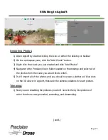
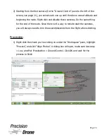
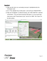
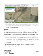
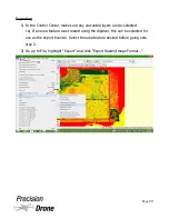
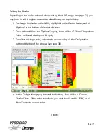
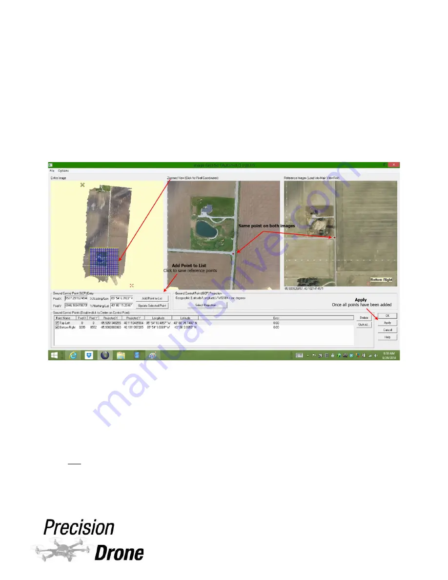
4) Now the Image Rectifier window will open, displaying the RGB map under 

“Zoomed View” and the NAIP satellite map under “Reference Images”. An Entire
Image view is also displayed. 

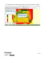
5) From here you add individual points to both the Reference image (NAIP map) 

and your map. So, Point 1 on the RGB map should match where Point 1 is on 

the NAIP map (Point 2 to Point 2, 3 to 3, etc.) Add as many points as possible, 
the more there are, the more accurate the rectification.
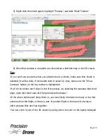
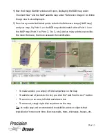
To make a point, you simply left click anywhere on the map

To add the set of points to the list, you click the “Add Point to List “ button

To zoom in on an area, left click and draw a box 

To zoom out, simply right click anywhere on the map

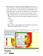
Tip: its really easy and recommended to establish points on objects that 

typically don't move over time, like crossroads, trees, driveways, houses, etc.

1

34

Page 33 

Содержание Pacesetter 2015

Страница 1: ...User s Manual Pacesetter Model 2015 Serial Number Version 1 12...

Страница 2: ...ything Charged 10 5 GPS Recalibration 11 6 Setting Up a Route 14 7 Pre Flight 17 8 Flight 18 9 Post Flight 21 10 Stitching In Agisoft 22 11 NDVI Creation using Global Mapper 29 12 Motor Rotation Diagr...

Страница 3: ...ne will land in place when it reaches less than 14 0v Keep away from spinning motors at ALL TIMES Do not attempt to modify the drone Do not attempt to repair the drone NEVER allow minors to charge bat...

Страница 4: ...th Never allow use of this product by anyone without providing them with these instructions You must read understand and follow all instructions and warnings for any product s to which this product is...

Страница 5: ...1x Precision Vision Camera NIR 1x Precision Vision Camera RGB 2x Camera Charger Access Cable 1x DX8 Controller 1x Controller Charger 1x Controller Strap 1x Bind Plug 1x Data Link 1x Data Link Cable 2...

Страница 6: ...Components DX8 Controller 1 6 Page 5...

Страница 7: ...Battery Charger 1 7 Page 6...

Страница 8: ...Live Feed Monitor 1 8 Page 7...

Страница 9: ...Modes GPS GPS and Gyroscope correction ATT Gyroscope correction only M Manual No GPS or Gyroscope correction Never fly when the screen says this GPS FS Failsafe mode Ghome Go home mode Drone will be...

Страница 10: ...Precision Vision Camera 1 10 Page 9...

Страница 11: ...st to the top as shown above Make sure the red wire is towards the bottom Make sure the checker is set for the correct battery type As shown above to the left of the total voltage it should read LiPo...

Страница 12: ...a power outlet The charging indicator LED will glow red It will turn green when finished Laptop battery percentage can also be checked in Windows in the lower right hand corner of the desktop Batteri...

Страница 13: ...there is an M in the lower left hand corner now when that switch is in position 2 This step allows you to be able to calibrate the GPS 5 Make sure you have AT LEAST 8 satellites before doing the next...

Страница 14: ...clination When first set the drones are programmed for true north in relation to Indiana If the drone does not fly straight where you are you will need to adjust the declination NOTE It is advised by...

Страница 15: ...1 15 Page 14...

Страница 16: ...sily Simply use it to search for a nearby address or latitude and longitude 3 Go up to Toolbox and click Photogrammetry Tool 4 Make sure the settings are correct Focal Length 35mm Sensor H 47mm Sensor...

Страница 17: ...e all of the waypoints are located 8 Clicking Generate will create the route you can now edit individual waypoints to fit the shape of the field Maintain the uniform flight pattern IMPORTANT Point 0 i...

Страница 18: ...1 18 Page 17...

Страница 19: ...see page 5 Make sure the throttle is all the way down 7 Turn on the controller 8 Make sure batteries are strapped in and tight 9 Power on your live feed monitor and check that voltage is normal it sh...

Страница 20: ...Position 0 GPS GPS is ON Gyro active Position 1 Att GPS is OFF Gyro active Position 2 FS Failsafe For emergency use only NOTE If you had to recalibrate the GPS as described on pages 11 12 make sure y...

Страница 21: ...the Pre Flight checklist and make sure everything is okay with the drone 4a Make sure the drone has acquired at least 8 satellites 5 With the drone powered on now and ready to go click Connect in Grou...

Страница 22: ...mpleted as the starting waypoint 4 Go to the last waypoint completed and set its turning mode to Stop and Turn 5 Upload the route to the Pacesetter and launch it 5a Make sure to take off manually and...

Страница 23: ...folder by right clicking highlighting New and click Folder Name it something you will remember 6 Within that folder create two more folders named IR and RGB This is so everything stays organized 6a Re...

Страница 24: ...to the Precision Vision folder located on the desktop and select all of the photos from the route you would like to stitch 5 It will import all of the photos and you should now see a plethora of blue...

Страница 25: ...me thing for the end of the route Since there isn t a way to remote start the cameras you will always need to trim the ascent descents from the flight when stitching Processing 1 Right click the chunk...

Страница 26: ...2 Right click the chunk again highlight Process and click Optimize Alignment Keep Fit k4 unselected 1 26 Page 25...

Страница 27: ...3 Right click the chunk again highlight Process and click Build Dense Cloud Set Quality to Lowest for faster results and set Depth Filtering to Aggressive for a proper orthophoto 1 27 Page 26...

Страница 28: ...click the chunk again highlight Process and click Build Mesh Select Height Field for the Surface Type Sparse Cloud for the Source Data and set the Polygon Count to High Keep Interpolation enabled 1 28...

Страница 29: ...the Show Cameras button on the top toolbar is highlighted If all of the photos don t align in the first process try selecting the cameras that don t align right click them and click Align Selected Cam...

Страница 30: ...hlight Export Orthophoto and click Export JPEG TIFF PNG 3 Make sure Geographic is selected at the top and Write World File is selected at the bottom If you will need to email the final photo or you ar...

Страница 31: ...ng it up 1 Open up Global Mapper by double clicking the icon on the desktop or clicking the taskbar icon 2 Open your RGB IR maps you created earlier with Agisoft by clicking on the Open Your Own Data...

Страница 32: ...e imagery by going to File and selecting Download Online Imagery Topo Terrain Maps 4 You want to select NAIP Color Imagery for US 1m resolution and click Connect If NAIP is not available use the World...

Страница 33: ...de map provided by the professional mapping sources This process should be as precise as possible so its as accurate an NDVI as can be in the end 1 Begin by deselecting the IR layer Click the check bo...

Страница 34: ...the NAIP map Point 2 to Point 2 3 to 3 etc Add as many points as possible the more there are the more accurate the rectification To make a point you simply left click anywhere on the map To add the se...

Страница 35: ...epeat the rectification process for the IR map now it is done exactly the same way as the RGB map Tip Use the slider tool at the top of the page see page 30 to see how well the RGB IR layers line up w...

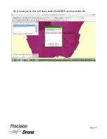
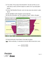
Страница 36: ...10 A Select Layers box will open select the RGB IR layers and click OK 1 36 Page 35...

Страница 37: ...fined Formula and in the drop down menu beside it select NDVI 13 Click Add Band and it will appear in the formula box 14 Click OK at the bottom the Set up Bands for Export window will appear 15 Select...

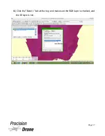
Страница 38: ...16 Click the Band 1 tab at the top and make sure the RGB layer is checked and the IR layer is not 1 38 Page 37...

Страница 39: ...you have several options on what to do with it including area calculations exporting as a KMZ file to be opened with Google Earth and exporting as a GeoTIFF for use in farm management software Other f...

Страница 40: ...ch the end of the perimeter you re mapping out right click 2 In the window that pops up name the area feature If mapping multiple fields use the field name If mapping hail damage it is easier to simpl...

Страница 41: ...s are de selected 1a If an area feature was created using the digitizer this can be selected for use as the export bounds Select the area feature desired before going onto step 2 2 Go up to File highl...

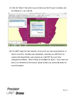
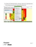
Страница 42: ...3 A Select Export Format window will pop up make sure GeoTIFF is selected 1 42 Page 41...

Страница 43: ...4 A window GeoTIFF Export Options will open make sure you enable the World File by checking the box next to Generate TFW World File 1 43 Page 42...

Страница 44: ...e is useful as it can be loaded into Google Earth on any device be it tablet smartphone or PC If it is loaded onto a device with GPS capabilities Such as a tablet or smartphone you will be able to use...

Страница 45: ...ect KML KMZ Any Data as Images 4 Select PNG as your image format 5 Under the Export Bounds tab select Crop to Selected Area Feature s 6 Hit OK and name the file It is suggested you name it after the f...

Страница 46: ...the bottom of the control center 2 Toward the middle of the Options pop up there will be a Shader drop down Select a different shader and hit apply 3 To edit an existing shader or to create a new shad...

Страница 47: ...s box and either hit Change Color or Change Value to edit the variable that is desired The value can only be between 1 and 1 Tip We suggest using the Precision Vision Shader for most crops If your Pac...

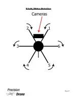
Страница 48: ...Blade Motor Rotation 1 48 Page 47...

Страница 49: ...1 49 Page 48...

Страница 50: ...5771M 5790M 5809M 5828M 5847M 5866M E 5705M 5685M 5665M 5645M 5885M 5905M 5925M 5945M F 5740M 5760M 5780M 5800M 5820M 5840M 5860M 5880M Sensitivity 90dbm 1dBm Channel 32 Channel 4 Band x 8 Channel An...

Страница 51: ...Flight and Service Log Serial Number...

Страница 52: ...Name of Pilot Technician Starting Voltage Ending Voltage Lowest Satellite Count Highest Satellite Count Total Flight Time Weather Conditions If flown within 5 miles of an airport Airport Date and Tim...

Страница 53: ...Name of Pilot Technician Starting Voltage Ending Voltage Lowest Satellite Count Highest Satellite Count Total Flight Time Weather Conditions If flown within 5 miles of an airport Airport Date and Tim...

Страница 54: ...Name of Pilot Technician Starting Voltage Ending Voltage Lowest Satellite Count Highest Satellite Count Total Flight Time Weather Conditions If flown within 5 miles of an airport Airport Date and Tim...

Страница 55: ...Name of Pilot Technician Starting Voltage Ending Voltage Lowest Satellite Count Highest Satellite Count Total Flight Time Weather Conditions If flown within 5 miles of an airport Airport Date and Tim...

Страница 56: ...Name of Pilot Technician Starting Voltage Ending Voltage Lowest Satellite Count Highest Satellite Count Total Flight Time Weather Conditions If flown within 5 miles of an airport Airport Date and Tim...

Страница 57: ...Name of Pilot Technician Starting Voltage Ending Voltage Lowest Satellite Count Highest Satellite Count Total Flight Time Weather Conditions If flown within 5 miles of an airport Airport Date and Tim...

Страница 58: ...Name of Pilot Technician Starting Voltage Ending Voltage Lowest Satellite Count Highest Satellite Count Total Flight Time Weather Conditions If flown within 5 miles of an airport Airport Date and Tim...

Страница 59: ...Name of Pilot Technician Starting Voltage Ending Voltage Lowest Satellite Count Highest Satellite Count Total Flight Time Weather Conditions If flown within 5 miles of an airport Airport Date and Tim...

Страница 60: ...Name of Pilot Technician Starting Voltage Ending Voltage Lowest Satellite Count Highest Satellite Count Total Flight Time Weather Conditions If flown within 5 miles of an airport Airport Date and Tim...

Отзывы: