Installation - Page 17
2.6
Flue Extension
The total length must not exceed 3 m.
If the length of the flue/terminal assembly is to be more than 600 mm, one, two or three flue extensions will have to be used
as follows:
1.
Carefully unpack the flue extension.
Supplied with the extension tube are six No.8 x 10 lg. screws and a small roll of sealing tape.
2.
Locate the flared end of the extension over the open end of the flue/terminal assembly. Ensure that the inner flue tubes
are engaged. If the length of the flue/terminal assembly is to be more than 1600 mm fit another flue extension to the
one just fitted in the same way. Similarly if the assembly is to more than 2600 mm fit another flue extension.
3.
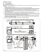
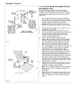
Mark the final extension (extension that will connect to the boiler) to the required length, measure from the back of the
terminal flange. See Fig.21.
4.
Cut the last tube squarely to the correct length (the one that will fit to the boiler) and remove all burrs.
5.
Install the flue assembly in the wall, See Fig.21 & slide the support brackets on the extension & connect up to the flue
assembly. Using the pilot holes in the flared end of the extension, drill three 2.8 mm dia. holes into the outer tube of the
flue/terminal assembly. Take care not to damage the inner flue tube with the drill.
Secure the extension to the flue/terminal assembly using the three screws supplied with the extension. Seal the joint
with the tape supplied with the extension. Bend the end of the support bracket/s so it joins a wall or ceiling member &
secure with two screws/plugs provided.
6.
Return to the section you were at before this one and carry on with the installation.
U
L
0
0
1
2
1
B
For flues with extensions, measure
from the boiler chassis flue hole to
the outside wall = X + 15mm
Outside
wall
Wedge the flue tube in a central position
Cut extension
off both flue &
air tubes square
(clean off burrs)
Connect up the OUTER
extension, drill 3 pilot
holes (per joint)
& screw together, seal
joints with tape
Support each
extension with the
support bracket
provided
Extensions
Flue Assembly
X + 15mm (maximum total flue length with extensions 3000mm)
wall liner
Inner
wall
Remove side
blanking plate
Boiler
Chassis
Measure and cut the right hand
side flue, (left hand opposite)
Connect the flue to the
boiler & secure together
Stage 1
Stage 2
Rubber
Gasket
Inner Wall
Seal
Take the Clamping
Plate & Sealing
Ring of the rear
flue outlet & fit the
side blanking plate
over the rear flue
hole. Slide the
gasket & plate
over the air tube
& secure to the
boiler chassis
with 4 screws
Fitted side blanking plate
to rear flue outlet
Out er
Wall
Plate
Mark,
drill,
plug &
secure
with 4
screws
Out er
Sealing
Plate
Fit the
white
side
panel
before
fitting
the side
flue
Flue
Terminal
Connect up the INNER extension, drill 3 pilot
holes (per joint) & screw together, seal
joints with tape
Fig 21
Содержание Ultra 2
Страница 6: ...Installation Requirements Page 6 Fig 1 ...
Страница 7: ...Installation Requirements Page 7 Fig 2 ...
Страница 9: ...Installation Requirements Page 9 ...
Страница 37: ...Routine Maintenance Page 37 ...
Страница 51: ...7 Wiring Diagrams Page 51 ...
Страница 52: ...Wiring Diagrams Page 52 Ultra 2Dv ...
Страница 53: ...Wiring Diagrams Page 53 Ultra 2 ...
Страница 54: ...54 Fault Finding Part No 405 0522 8 Fault Finding Guide Page 54 ...
Страница 55: ...Part No 405 0522 Fault Finding 55 Fault Finding Guide Page 55 ...
Страница 56: ...56 Fault Finding Part No 405 0522 Fault Finding Guide Page 56 ...
Страница 57: ...Part No 405 0522 Fault Finding 57 Fault Finding Guide Page 57 ...
Страница 58: ...9 Short List Of Spare Parts Page 58 ...


