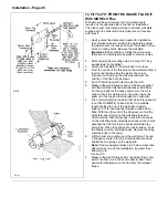
Installation - Page 12
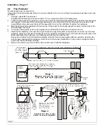
H,I
K
G
D
F
J
N
A
P
R
Q
Q
S
N
UL00110C
N
A
A
B,C
B,C
C
E
F
G
G
G
G
K
L
L
K
K
F
F
U
L
0
0
0
5
3
C
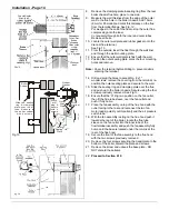
Fig. 8
Dim.
Terminal Position (Fanned Balanced Flue models)
Min. Spacing
A
Directly below an opening, air brick, window, etc.
300
B
Below gutters, soil pipes or drain pipes
75 *
C
Below eaves
200 *
D
Below balconies or car port roofs
200
E
From a vertical drain pipe or soil pipe
75
F
From an internal or external corner
25
G
Above ground, roof or balcony level
300 **
H
From a surface facing the terminal
600
I
From a terminal facing the terminal
1200
J
From an opening in the car port (e.g. door, window) into dwelling
1200
K
Vertically from a terminal on the same wall
1500
L
Horizontally from a terminal on the same wall
300
N
Above roof level (to base of terminal)
300
P
From adjacent wall to flue
210
Q
From internal corner to flue
230
R
Below eaves or balcony
600
S
From facing terminal
1200
*If the terminal is fitted within 850mm of a plastic or painted
gutter/pipe or 450mm of painted eaves, an aluminium shield of
at least 750mm in length should be fitted to the underside of the
gutter/pipe or painted surface.
** If the terminal is fitted less than 2m above a balcony, above
ground or above a flat roof to which people have access, then a
suitable terminal guard must be provided and fitted.
A type K1 (G.C. No. 393 552) protective guard is available from Tower Flue Components Ltd. at: Vale Rise, Tonbridge, Kent TN9
1TB, Tel: (01732) 351555. The guard must be securely fitted to the wall and centrally located over the flue terminal. Refer to the
manufacturers instructions.
2.3
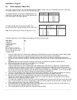
Fit the Optional Wall Spacing Kit
The wall spacing kit allows the boiler to be spaced 40 mm from
the wall, providing sufficient room for all pipework to be run
behind the boiler.
Kit Contents
Item
Qty
Spacing Plate
1
M6 x 12lg Screw
5
1.
Decide upon the position of the boiler using the wall plate
supplied with the boiler. Ensure that the wall plate is level
and mark the centre lines of the flue opening onto the wall.
Using these lines as a guide mark the positions of the six
spacing plate fixing holes you will use (12 holes are
provided to avoid drilling into mortar). Drill and plug these
holes to accept 2½" lg. No.12 woodscrews.
2.
If rear exit flue is to be used, cut the hole in the wall before
fitting the spacing plate.
3.
Secure the spacing plate to the wall with six 2½" lg. No.12
woodscrews (not supplied).Ensure that the spacing plate is
level.
4.
Secure the wall plate, supplied with the boiler, to the
spacing plate with the five screws supplied with this kit.
5.
Continue to install the boiler as described in the relevant
flue section.
IMPORTANT
As the boiler is now spaced off the wall by 40mm, all
dimensions quoted in the flue sections for the position of
the flue in relation to the wall must be increased by 40mm.
Содержание Ultra 2
Страница 6: ...Installation Requirements Page 6 Fig 1 ...
Страница 7: ...Installation Requirements Page 7 Fig 2 ...
Страница 9: ...Installation Requirements Page 9 ...
Страница 37: ...Routine Maintenance Page 37 ...
Страница 51: ...7 Wiring Diagrams Page 51 ...
Страница 52: ...Wiring Diagrams Page 52 Ultra 2Dv ...
Страница 53: ...Wiring Diagrams Page 53 Ultra 2 ...
Страница 54: ...54 Fault Finding Part No 405 0522 8 Fault Finding Guide Page 54 ...
Страница 55: ...Part No 405 0522 Fault Finding 55 Fault Finding Guide Page 55 ...
Страница 56: ...56 Fault Finding Part No 405 0522 Fault Finding Guide Page 56 ...
Страница 57: ...Part No 405 0522 Fault Finding 57 Fault Finding Guide Page 57 ...
Страница 58: ...9 Short List Of Spare Parts Page 58 ...


