Installation - Page 20
Flue
Terminal
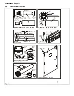
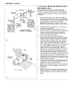
Drill 3 pilot holes
in flue tube
(2.8mm dia.)
& screw together.
Slide the air tube
over flue tube &
secure in position
using the
same method,
as the
inner flue.
Extension
(flue tube)
Extension
(air tube)
U
L
0
0
1
1
9
B
Wedge the
flue tube
in a
central
position
Extension
Seal this joint
with tape supplied
Cut extension
off both flue &
air tubes square
(clean off burrs)
Flue
Terminal
Pilot holes
(3 off)
Stage 1
Stage 2
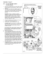
Drill 3 holes
through
2.8mm dia.
& secure
flue with
No. 8 x 10Lg
screws
Vertical flue
adaptor
Gasket
Unscrew 3
fixing screws
& rotate
fan motor
Inner tube
of flue
M4 x 16Lg Screws (4 off)
NOTE:
The flue
tubes
MUST
NOT
protrude
past this
face
Flue tube
sleeve on
fan outlet
Support bracket
should be at
the bottom
U
L
0
0
1
1
5
B
Fig. 24
Retain the adaptor for connection of the flue system to
the boiler.
13. The Vertical Balanced Flue MUST be installed from the
roof !
Carefully lower the flue assembly, complete with collar
and flashing, down through the previously prepared
holes in the roof, internal ceilings and floors. Secure the
sealing plate in position with four 1 in long No.8
woodscrews, not supplied. Temporarily support the flue
clear of the boiler position and proceed to fit the boiler.
14. Lift the boiler into position over the wall plate. The two V
shaped cut outs in the top mounting bracket locate
behind the two prongs on the wall plate. Take care not
to damage the flue.
15. Insert a woodscrew (not supplied) into the bottom fixing
hole to secure the boiler to the wall.
16. Remove the sealing ring and clamping plate from the
rear of the chassis, remove the sealing plate and four
fixing screws from the top of the chassis and fit this to
the rear of the chassis.
17. Remove the four screws securing the fan to the flue
diverter, rotate the fan so that the outlet is facing
upwards and secure it to the diverter with the four
screws previously removed. Remove the 3 screws
securing the fan motor to the fan assembly. Rotate the
motor so that the motor support is again positioned at
the underside of the fan.
18. Replace the fan assembly on top of the flue hood.
Reconnect the fan motor leads (polarity not important)
and air pressure switch tube.
19. With the fan assembly resting on the flue hood push it
to towards the rear of the boiler locating the base under
the returns at the rear of the flue hood. Secure the front
of the fan assembly to the flue hood with the two
screws previously removed.
20. Position the gasket and vertical flue adaptor in position
on top of the chassis and secure in place with four M4 x
16 mm long hex. head screws - all supplied with the
Vertical Balanced Flue kit.
21. Pass the flue tube sleeve down through the adaptor
and over the fan outlet and push fully home.
22. Lower the flue system down into the adaptor, ensuring
that the inner tube of the flue locates over the flue tube
sleeve on the fan outlet. Secure the flue to the adaptor
using the three No.8 x 10 mm long screws, supplied
with the kit, into the three pilot holes previously drilled.
23. Having secured the flue system to the boiler, proceed to
make good the roof joint and refit the flue terminal cowl
to the terminal die-casting. Secure the assembly using
nine No.8 x 12 mm long screws supplied with the kit.
24. Proceed to Section 2.10
Содержание Ultra 2
Страница 6: ...Installation Requirements Page 6 Fig 1 ...
Страница 7: ...Installation Requirements Page 7 Fig 2 ...
Страница 9: ...Installation Requirements Page 9 ...
Страница 37: ...Routine Maintenance Page 37 ...
Страница 51: ...7 Wiring Diagrams Page 51 ...
Страница 52: ...Wiring Diagrams Page 52 Ultra 2Dv ...
Страница 53: ...Wiring Diagrams Page 53 Ultra 2 ...
Страница 54: ...54 Fault Finding Part No 405 0522 8 Fault Finding Guide Page 54 ...
Страница 55: ...Part No 405 0522 Fault Finding 55 Fault Finding Guide Page 55 ...
Страница 56: ...56 Fault Finding Part No 405 0522 Fault Finding Guide Page 56 ...
Страница 57: ...Part No 405 0522 Fault Finding 57 Fault Finding Guide Page 57 ...
Страница 58: ...9 Short List Of Spare Parts Page 58 ...

