Installation - Page 19
1.
Carefully unpack the kit, do not discard the packaging until all the items are found. The sealing ring and clamping plate
supplied with the boiler are not required when the Vertical Balanced Flue kit is used and should be discarded.
2.
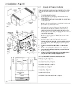
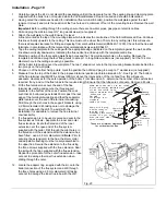
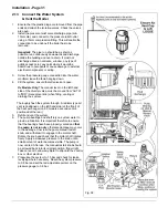
Having noted the clearances needed for installation (flue terminal & boiler), position the wall plate against the wall
(ensure it is level) and mark the position of the flue hole and a minimum of four of the mounting holes. Remove the wall
plate.
Important:
Before cutting through the ceiling ensure there are no water pipes, gas pipes or electric cables.
3.
Drill and plug the wall to accept 2½" long woodscrews (not supplied).
4.
Attach the wall plate to the wall. Ensure it is level.
A line is marked at the top of the mounting plate which indicates the centre line of the Vertical Balanced Flue. Continue
this line vertically upwards to the ceiling. This line must not be closer than 75 mm to any ceiling joist, this will ensure
there is adequate clearance for fitting and spacing from combustible material (BS5440:1:1990). Check that the flue will
terminate in accordance with the relevant recommendations given in BS5440:1.
5.
Tape the ceiling template to the ceiling with the appropriate edge (indicated on the template) against the wall, and the
line drawn vertically downwards, indicating the flue centre line, lined up with the template centre line.
6.
Mark the position of the four sealing plate fixing holes and the 134 mm diameter hole on the ceiling. Remove the
template and drill and plug the four fixing holes to accept 1 in long No.8 woodscrews (not supplied). Cut the 134 mm
diameter hole in the ceiling as neatly as possible.
7.
Lift the boiler into position over the wall plate. The two V shaped cut outs in the top mounting bracket locate behind the
two prongs on the wall plate.
8.
Choose on of the bottom fixing points, mark the position then drill and plug to accept a 1" woodscrew (not supplied).
9.
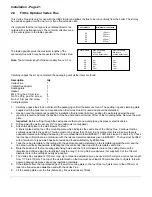
Measure from the top of the boiler to the proposed terminal position to obtain dimension ‘A’ - See Fig. 22. The bottom
of the flue terminal cowl MUST be at least 300 mm above the inter-section of the roof and flue, this will ensure
adequate clearances for the safe operation of the boiler. From dimension ‘A’, determine the number of flue extensions
required, if any, and cut the flue tubes to the required length. Ensure that the tubes are cut square. Remove all burrs.
10.
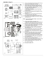
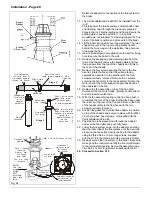
Fit the flue terminal cowl over the end of the flue
terminal die-casting and secure the three support
brackets to the bottom of the cowl. Position the cowl
such that it’s bottom edge extends 30 mm past the rear
edge of the terminal die-casting and that the separator
plate locates over the end of the terminal die-casting.
Drill through the six holes in the support brackets, using
a 2.8mm diameter drill, taking care not to damage the
inner flue tube with the drill. To assist with the
installation it is advisable to remove the flue terminal
cowl assembly.
11.
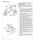
If a flue extension is to be used, secure and seal to the
flue system as follows:- Separate the inner and outer
flue extensions, locate the flared end of the inner
extension over the open end of the flue system
supplied with the boiler. Drill through the pilot holes, in
the flared end of the extension after the extension has
been fitted - use a 2.8 mm diameter drill.
Note:
Prior to
securing the extension(s) to the flue, the storm collar
and adjustable flashing must be loosely assembled to
the upper flue. Secure the extension to the flue using
the three screws supplied with the flue extension. Seal
the joint with the tape supplied with the flue extension.
Repeat the procedure for the outer flue extension - take
care not to damage the inner flue extension when
drilling through the outer.
12.
Locate the adaptor ring, supplied with the kit, onto the
boiler connection of the flue system and drill through
the three holes using a 2.8 mm diameter drill, taking
care not to damage the inner flue tube with the drill.
U
L
0
0
1
0
9
B
36mm
Side
Clearance
Spirit
Level
36mm Side
Clearance
515mm
Bottom
Clearance
Mark the centre line up to the ceiling
& with the sealing template mark
off t he flue centre. Cut a
134mm diameter hole.
Make sure you
DO NOT
cut through roof
members,
cables Or Pipes
These are minimum clearances
for vertical/vertex flue
170mm
Sealing
Template
Mark, drill & plug
4 holes ready to
take the wall
mounting plate securing
screws, (if a you hit a
brick joint use other
holes provided).
Fig. 23
Содержание Ultra 2
Страница 6: ...Installation Requirements Page 6 Fig 1 ...
Страница 7: ...Installation Requirements Page 7 Fig 2 ...
Страница 9: ...Installation Requirements Page 9 ...
Страница 37: ...Routine Maintenance Page 37 ...
Страница 51: ...7 Wiring Diagrams Page 51 ...
Страница 52: ...Wiring Diagrams Page 52 Ultra 2Dv ...
Страница 53: ...Wiring Diagrams Page 53 Ultra 2 ...
Страница 54: ...54 Fault Finding Part No 405 0522 8 Fault Finding Guide Page 54 ...
Страница 55: ...Part No 405 0522 Fault Finding 55 Fault Finding Guide Page 55 ...
Страница 56: ...56 Fault Finding Part No 405 0522 Fault Finding Guide Page 56 ...
Страница 57: ...Part No 405 0522 Fault Finding 57 Fault Finding Guide Page 57 ...
Страница 58: ...9 Short List Of Spare Parts Page 58 ...

