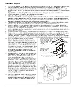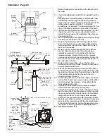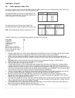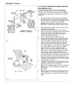
Commissioning - Page 33
3.
Check the ignition sequence.
With the gas supply isolated check the ignition sequence as follows:
a.
Set the test switch to 'Override'.
Note:
Three indicator lamps are included on the ignition board to aid electrical commissioning. The correct
sequence of lights when there is a call for heat is: Permanent Live 'On', Switched Live 'On', Reversed Polarity 'Off'.
b.
Switch on the electricity supply and turn the thermostat knob fully clockwise. The automatic ignition sequence will
commence. The fan will start and after a short purge period a click will be heard indicating that the start gas
solenoid has opened, ignition sparks will also be heard. The ignition sparks will continue until the pilot is lit but as
the gas supply is not yet turned on the ignition sparks will continue until either the electricity supply is switched off or
the thermostat knob is turned off (fully anti-clockwise).
c.
Turn the thermostat knob fully anti-clockwise to terminate the ignition sequence.
4.
Check the pilot flame and test the pilot supply for gas soundness.
a.
Ensure that the gas and electricity supplies are on, the thermostat knob is turned fully anti-clockwise and the test
switch is set to 'Override'.
b.
Turn the thermostat knob fully clockwise. The unit will go through the ignition sequence. The pilot will light and a
second or so after the pilot has lit the main gas solenoid will open and the main burner will light.
c.
During the short pilot only period, check that the flame is 35 to 40 mm long and envelops the electrode.
The pilot throttle is factory set fully open (turning the throttle clockwise reduces the flame).
d.
Turn the thermostat knob fully anti-clockwise. Re-fit the combustion chamber cover and secure with the screws
previously removed. Turn the thermostat knob fully clockwise, to relight the boiler.
e.
Test the pilot supply connections at the gas valve and pilot assembly for gas soundness using a suitable leak
detecting fluid.
f.
Turn the thermostat knob fully anti-clockwise.
5.
Test the main burner supply for gas soundness.
a.
Ensure that the gas and electricity supplies are on, the thermostat knob is turned fully anti-clockwise and the test
switch is set to 'Override'.
b.
Turn the thermostat knob fully clockwise. The unit will go through the automatic ignition sequence and the pilot will
light. A second or so after the pilot is lit the main gas solenoid will open and the main burner will light.
c.
Test the main burner manifold connection at the gas valve for gas soundness using a suitable leak detecting fluid.
6.
Check the main burner setting pressure.
After the main burner has been alight for 10 minutes:
a.
Turn the thermostat knob fully anti-clockwise. Remove the burner pressure test point screw on the gas valve and
connect a pressure gauge. The pressure increases in two stages, to a 1st step for a few seconds then to full
pressure.
Note:
The boiler is factory set to the maximum input, the 1st step pressure is also factory set and should not require
further adjustment. See Technical Data, Page 3, for the boiler ratings and setting pressures.
The adjusting screw is covered by a plastic cap, carefully prise this off with a suitable screwdriver and replace after
adjusting the pressure.
b.
Turn the thermostat knob fully clockwise and check the burner setting pressure.
Turn the adjusting screw clockwise to decrease the setting pressure.
c.
Turn the thermostat knob fully anti-clockwise, disconnect the pressure gauge and replace the pressure test point
screw. Turn the thermostat knob fully clockwise to light the main burner and test for gas soundness around the
pressure test point screw using a suitable leak detecting fluid. Turn the thermostat knob fully anti-clockwise to turn
the boiler off.
7.
Complete the commissioning.
a.
Check that the arrow on the data label (positioned on the left hand side of the chassis next to the gas valve) is
against the correct boiler rating.
b.
Switch off the electricity supply to the boiler.
c.
Set the test switch to 'Normal' if a programmer or external controls are used.
Note:
The pilot burner is turned off every time the main burner is off. The ignition sequence is automatically activated
when the boiler thermostat requires heat. The boiler is fitted with two neons, a green one that lights when the main
burner is alight and a red neon that will light if the boiler has locked out. If the boiler does lock out a re-set button is
located under the front of the boiler at the right hand side.
Содержание Ultra 2
Страница 6: ...Installation Requirements Page 6 Fig 1 ...
Страница 7: ...Installation Requirements Page 7 Fig 2 ...
Страница 9: ...Installation Requirements Page 9 ...
Страница 37: ...Routine Maintenance Page 37 ...
Страница 51: ...7 Wiring Diagrams Page 51 ...
Страница 52: ...Wiring Diagrams Page 52 Ultra 2Dv ...
Страница 53: ...Wiring Diagrams Page 53 Ultra 2 ...
Страница 54: ...54 Fault Finding Part No 405 0522 8 Fault Finding Guide Page 54 ...
Страница 55: ...Part No 405 0522 Fault Finding 55 Fault Finding Guide Page 55 ...
Страница 56: ...56 Fault Finding Part No 405 0522 Fault Finding Guide Page 56 ...
Страница 57: ...Part No 405 0522 Fault Finding 57 Fault Finding Guide Page 57 ...
Страница 58: ...9 Short List Of Spare Parts Page 58 ...

