What the Eagle™ Records
••••
71
The default setting for triggering a current waveform is 40%. If
you wish to capture more or less current waveforms, simply set
this value higher or lower. If you do not wish to capture any
waveforms based on variations in current, simply set this
percentage to a very high level, so that it is unlikely that a
waveform will ever be triggered by a current variation (the highest
allowed trigger threshold is 900%).
A waveform capture report consisting of just one very long record
is an indication that the setting is too small. A report where all the
waveform records occurred during the last few minutes of the
recording session is another indicator of too small a threshold. In
both these cases, the trigger was being met too often. Of course,
if no waveform records are present, either the threshold was too
large, or the voltage quality was too good. The optimal setting
varies from system to system.
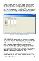
The exact nature of a voltage disturbance can be seen in the
waveform capture report. The peak voltage, length of the sag or
swell, and the coupling from phase to phase are easily seen in the
graph. Sometimes there are clues regarding the cause of a
voltage disturbance. A voltage sag that starts in the middle of a
cycle but ends at a zero crossing can be produced by a gas
arrestor. The arc continues until the voltage reaches zero, then
the arc is extinguished. A recloser operation usually begins and
ends at random points in the cycle. A voltage sag that is
preceded by an increase in current, but followed by a decrease in
current, is usually caused by the monitored load. If the current
went down during the sag, and was steady before and after, the
sag was probably not caused by the monitored load. Each
triggered event is often captured by the significant change and
event change reports. The minimum or maximum voltage is
usually in the interval graph as well. These reports can be used to
place the waveform capture record into the proper overall context.
Use the timestamps for each record type to correlate the different
reports.
A manual trigger captures the voltage and current waveforms
during steady state conditions (unless the user happened to press
the button at the exact moment of a disturbance). Transformer
Содержание Eagle 220
Страница 2: ......
Страница 3: ...Eagle Power Quality Recorder User s Manual...
Страница 8: ......
Страница 12: ......
Страница 14: ......
Страница 32: ...Connecting the Eagle 24 Figure 8 Eagle Hookup Diagrams...
Страница 38: ......
Страница 42: ......
Страница 90: ......
Страница 95: ......
Страница 96: ......

