Copyright Planika Sp. z o.o.
www.planikafires.com
IG0139#02
30.07.2018
13
5.4.
Electrical connection
Fireplaces MONROE requires connection to the mains 230V and should be connected by a person with the
appropriate permissions. Remember to use electric cables in the heat-resistant insulation and place them
away from the hot parts of the fireplace and installation elements. Electrical components of the gas valve
control unit are sensitive to dirt and dust generated during the assembly process of making fireplace housing.
Remember to protect against dust and moisture, all electrical components of the fireplace until their final
assembly. The electrical connection is completed with triple cube (L, N, PE)
WARNING!
Power must be connected only after connecting the air combustion system with all elements of
the gas control system.
5.4.1.
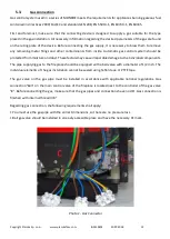
Connecting additional lighting or other electric receivers
Electronics that control the gas valve gives you the ability to connect an optional lighting (for example, to
highlight the interior of the housing) and allows you to control it from the remote control and automation of
intelligent building. The exact description of additional lighting control (or other electrical receiver) is
described in the user manual.
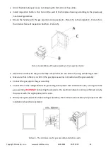
A built-in relay
"L"
can be used to control any AC receiver (AC 230V/0,5A). The relay has neutral polarity.
Connector
"B"
is used for connection of an additional fan or optional throttle (max 230V AC/0,8A) eg. to
improve air circulation within the housing or to distribute warm air from inside the housing to the other rooms.
Connector
"M"
is used for connecting additional gas solenoid, whose task is to turn on and off the side section
of the hearth.
Connector
"D"
gives the possibility to use an alternative method of controlling the fireplace (as described in
section 6.2.1). and integrate it through a wired connection with Intelligent Smart Home System (Domotica).
Connector
"F"
is used to connect the fan (with feedback to the driver), mounted on the air combustion wire,
supporting the chimney draft (max 230V AC / 0.8A). This connector cannot be controlled with the remote
control and operates independently from the user.
This connector is not active.
Photo 2 - Diagram of electrical connections
Содержание MONROE 900 F
Страница 43: ...Copyright Planika Sp z o o www planikafires com IG0139 02 30 07 2018 43 ...
Страница 45: ...Copyright Planika Sp z o o www planikafires com IG0139 02 30 07 2018 45 ...
Страница 65: ...Copyright Planika Sp z o o www planikafires com IG0139 02 30 07 2018 65 MONROE 900 FR MONROE 900 LFR ...


