5.5 High Dynamic Range (multiple slope) Mode
5.5
High Dynamic Range (multiple slope) Mode
To have an accurate laser line detection it is important that the pixels that represent the laser
line, are not saturated. The High Dynamic Range (HDR) mode is a special integration mode
that increases the dynamic range of the pixels, and thus avoids the saturation of the pixels in
many cases. The HDR mode is also called multiple slope mode or piecewise linear mode.
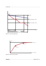
The HDR (multi slope) mode clips illuminated pixels which reach a programmable voltage,
while leaving the darker pixels untouched (see Fig. 5.33). The clipping level can be adjusted
once (2 slopes) or twice (3 slopes) within the exposure time.
Parameters:
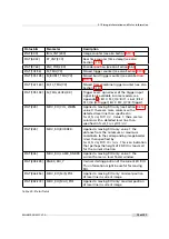
Multislope_Mode
There are 3 predefined HDR parameter sets:
LowCompression
,
NormalCompression
and
HighCompression
. If
Multislope_Mode
is set to
UserDefined
then the
individual parameters can be set to user defined values.
Multislope_NrSlopes
Number of slopes.
Multislope_NrSlopes
=2: 2 slopes with only knee point
B.
Multislope_NrSlopes
=3: 3 slopes with knee points A and B.
Multislope_Value1
Corresponds to Vlow1: the higher the value, the higher the compression.
Multislope_Time1
Time corresponding to knee point B. The value is the fraction (per mill) of
the total exposure time.
Multislope_Value2
Corresponds to Vlow2: the higher the value, the higher the compression.
This value is ignored if
Multislope_NrSlopes
=2.
Multislope_Time2
Time corresponding to knee point A. The value is the fraction (per mill) of
the total exposure time. This value is ignored if
Multislope_NrSlopes
=2.
The red line in Fig. 5.33 shows a pixel with high illumination. Without the HDR (3 slopes)
mode, the pixel would have reached its saturated value. With HDR mode, the pixel reaches
value P1 which is below the saturation value. The resulting pixel response in this case is shown
in Fig. 5.34. The blue line (P2) shows a pixel with low illumination. Its value never reaches
Vlow2 or Vlow1 at the knee points and the resulting response is linear.
The parameters
Multislope_Value1
and
Multislope_Value2
are only applied after
a camera trigger. Note that in free-running mode the camera trigger is applied
internally by the camera itself.
MAN075 05/2017 V1.0
69 of 127
Содержание MV1-D2048-3D06 series
Страница 1: ...Photonfocus MV1 D2048 3D06 Camera Series 3D CMOS camera with GigE interface MAN075 05 2017 V1 0...
Страница 10: ...1 Preface 10 of 127 MAN075 05 2017 V1 0...
Страница 12: ...2 Introduction 12 of 127 MAN075 05 2017 V1 0...
Страница 16: ...3 How to get started 3D GigE G2 Figure 3 3 PFInstaller components choice 16 of 127 MAN075 05 2017 V1 0...
Страница 26: ...3 How to get started 3D GigE G2 26 of 127 MAN075 05 2017 V1 0...
Страница 32: ...4 Product Specification 32 of 127 MAN075 05 2017 V1 0...
Страница 66: ...5 Functionality 66 of 127 MAN075 05 2017 V1 0...
Страница 82: ...6 Precautions 82 of 127 MAN075 05 2017 V1 0...
Страница 120: ...12 Support and Repair 120 of 127 MAN075 05 2017 V1 0...
Страница 122: ...13 References 122 of 127 MAN075 05 2017 V1 0...
Страница 127: ...C Revision History Revision Date Changes 1 0 May 2017 First version MAN075 05 2017 V1 0 127 of 127...


